Velocity Planner: Speed Profile Generation
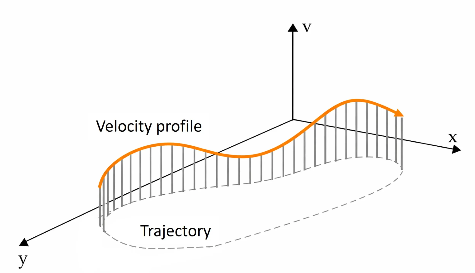
Velocity Planner is a module that generates optimal speed profiles for given waypoints while considering the vehicle’s dynamic constraints. It aims to maximize driving efficiency while ensuring driving stability within the vehicle’s physical limits.
| Feature | Description |
|---|---|
| Physics-based constraints | Considers tire friction, motor/brake limits, air resistance |
| Forward-Backward Solver | Speed planning algorithm considering acceleration & deceleration constraints |
| GGV Diagram | Expresses longitudinal/lateral acceleration limits by speed |
| Real-time | Fast computation (analytical solution) |
| Path-dependent | Dynamic speed adjustment based on curvature |
Physics Constraints
Friction Circle (Tire Acceleration Constraints)
The total acceleration that tires can provide is limited by friction. Longitudinal (acceleration/braking) and lateral (cornering) accelerations cannot occur independently, and their combination has a fixed limit. This constraint is generalized as the Generalized Friction Circle (Ellipse) model.
\[\left(\frac{a_x}{a_{x,max}}\right)^p + \left(\frac{a_y}{a_{y,max}}\right)^p \leq 1\]- $a_x$ : Longitudinal acceleration (acceleration/deceleration)
- $a_y$ : Lateral acceleration (cornering)
- $a_{x,max}$ : Tire longitudinal acceleration limit
- $a_{y,max}$ : Tire lateral acceleration limit
- $p$ : Dynamic model exponent (determines combined-slip shape, typically 1.0~2.0)
Higher $p$ values allow more aggressive acceleration. The friction circle shape varies as follows:
| $p$ | Friction Circle Shape | Characteristics |
|---|---|---|
| 1.0 | Diamond (◇) | Very conservative, strong corner acceleration limits |
| 1.5 | Intermediate | Balance between stability and performance |
| 2.0 | Circle / Ellipse (○) | Aggressive, allows acceleration in corners |
Acceleration Calculation
The lateral acceleration used during driving is calculated from curvature:
\[a_{y,used} = \frac{v^2}{r}\]Substituting into the Friction constraint, the available longitudinal acceleration is:
\[a_{x,avail} = a_{x,max} \cdot \left(1 - \left(\frac{a_{y,used}}{a_{y,max}}\right)^p\right)^{1/p}\]- On straight sections $(a_y = 0)$, $a_x = a_{x,max}$, allowing maximum acceleration.
- When entering corners ($a_y$ increases), $a_x$ decreases, limiting acceleration.
Therefore, the more steering input, the smaller the available acceleration.
Air Resistance
As speed increases, additional deceleration occurs due to air resistance.
\[a_{drag} = -\frac{c_d \cdot v^2}{m_{veh}}\] \[c_d = 0.5 \cdot C_w \cdot A_{front} \cdot \rho_{air}\]- $c_d$ : Drag coefficient
- $m_{veh}$ : Vehicle mass
Air resistance increases rapidly with speed, limiting acceleration performance at high speeds and determining the final acceleration limit together with tire friction constraints.
Algorithm (Forward-Backward Solver)
Principle (Two-pass Velocity Planning)
The Forward-Backward two-pass algorithm is used to calculate drivable speeds along the path.
- Forward Pass: Considering the vehicle’s acceleration capability, calculate the maximum achievable speed from current to next position.
- Backward Pass: Considering the vehicle’s deceleration capability, calculate the maximum allowable speed in reverse to safely reach the next position.
The final speed at each point is selected as the smaller value between Forward and Backward results, generating a speed profile that satisfies all dynamic constraints.
Steps
Step 1: Initial Speed Profile (Lateral G Constraint)
For a path with given curvature ($\kappa$), calculate the maximum speed satisfying the tire’s lateral acceleration limit.
\[v_{max}(i) = \sqrt{\frac{a_{y,max}}{|\kappa(i)|}}\]- $a_{y,max}$ : Maximum lateral acceleration of tires
- $\kappa(i)$ : Curvature at point $i$ (1/radius)
This step provides the theoretical maximum speed considering only cornering limits.
Step 2: Forward Pass (Acceleration Limit)
Proceeding from the start point along the path, calculate the maximum speed at the next point considering available longitudinal acceleration.
\[v_{i+1} = \sqrt{v_i^2 + 2 \cdot a_{x,avail} \cdot \Delta s}\]- $a_{x,avail}$ : Available longitudinal acceleration considering tires, motor, and air resistance
- $\Delta s$ : Distance between points $i \rightarrow i+1$
This step reflects the range within which the vehicle can actually accelerate.
Step 3: Backward Pass (Deceleration Limit)
Traveling backwards from the end point to the start, calculate safe deceleration speeds considering brake performance.
\[v_i = \sqrt{v_{i+1}^2 + 2 \cdot a_{x,brake} \cdot \Delta s}\]This ensures deceleration is possible in advance to meet the required speed at the next point.
Step 4: Final Speed Determination
Select the smaller value between Forward and Backward Pass results at each point.
\[v_{final}(i) = \min(v_{forward}(i), v_{backward}(i))\]Through this process, a speed profile satisfying all constraints including acceleration limits, deceleration limits, tire friction constraints, and air resistance can be generated.
GGV Diagram and Powertrain Constraints
To reflect acceleration performance changes with speed, GGV Diagram and motor/brake constraints are used together.
GGV Diagram
The table below summarizes maximum longitudinal and lateral accelerations the vehicle can generate at different speeds.
| Speed (v) | Max Longitudinal ($a_{x,max}$) | Max Lateral ($a_{y,max}$) |
|---|---|---|
| 0 m/s | 7.0 m/s² | 5.8 m/s² |
| 4 m/s | 7.0 m/s² | 5.8 m/s² |
| 8 m/s | 7.0 m/s² | 5.8 m/s² |
| 12 m/s | 7.0 m/s² | 5.8 m/s² |
By providing $a_{x,max}$ and $a_{y,max}$ values of the Friction Circle (Ellipse) by speed, it serves as basic input data for cornering limits and acceleration calculations.
Powertrain Constraints (Motor / Brake Limits)
Even if tires allow, actual acceleration/deceleration performance is additionally limited by motor output and brake performance.
Motor Acceleration Limit (ax_max_machines.csv):
| Speed | Max Motor Acceleration |
|---|---|
| 0-15 m/s | 4.2 m/s² |
The maximum driving acceleration the motor can generate, determining the upper limit of actual acceleration performance on straights.
Brake Deceleration Limit (b_ax_max_machines.csv):
| Speed | Max Brake Deceleration |
|---|---|
| 0-15 m/s | -7.0 m/s² |
Maximum brake deceleration performance, used to determine deceleration capability in the Backward pass.
Integration in Algorithm
Forward Pass (Acceleration)
\[a_{x,avail} = \min(a_{x,tires}, a_{x,motor}) + a_{drag}\]Select the smaller value between tire friction limit and motor performance as the acceleration upper limit, then add air resistance deceleration to calculate actual available longitudinal acceleration.
Backward Pass (Deceleration)
\[a_{x,avail} = \min(a_{x,tires}, a_{x,brake}) + a_{drag}\]Calculate deceleration limits considering both tire constraints and brake performance. Air resistance that increases proportionally with speed is added, changing effective deceleration performance at high speeds.
Implementation and Usage
Configure the main function calc_vel_profile() with required inputs (ggv, kappa, el_lengths, etc.) and options as follows:
1
2
3
4
5
6
7
8
9
10
11
12
13
vx_profile = calc_vel_profile(
    ggv=ggv,                        # g-g diagram
    ax_max_machines=ax_max,         # Motor limits
    b_ax_max_machines=b_ax_max,     # Brake limits
    kappa=kappa,                    # Curvature array
    el_lengths=el_lengths,          # Distance between waypoints
    closed=True/False,              # Closed loop flag
    v_max=12.0,                     # Maximum speed
    v_start=cur_v,                  # Start speed (open loop only)
    dyn_model_exp=1.0,
    drag_coeff=0.0136,
    m_veh=3.5
)
Usage Scenarios
Raceline optimization (offline)
Use closed=True setting for one lap of the track to calculate speed profile. Once calculated, the saved result is reused for subsequent driving.
Local planning (runtime)
Use closed=False setting to calculate speed only for a certain section ahead from the current vehicle position. Using v_start=current_speed, periodically recalculate the speed profile during driving to respond to environmental changes such as static obstacles.
Parameter Tuning
Parameter Files
Vehicle Parameters: config/{CAR_NAME}/racecar_f110.ini
1
2
3
4
5
6
7
8
9
10
[GENERAL_OPTIONS]
veh_params = {
    "v_max": 12.0,          # Maximum speed (m/s)
    "mass": 3.5,            # Vehicle mass (kg)
    "dragcoeff": 0.0136     # Air resistance coefficient
}
vel_calc_opts = {
    "dyn_model_exp": 1.0,                   # Diamond model
    "vel_profile_conv_filt_window": 51      # Filter window (odd number)
}
GGV Diagram: config/{CAR_NAME}/veh_dyn_info/ggv.csv
# v_mps, ax_max_mps2, ay_max_mps2
0.0,  7.0, 5.8
4.0,  7.0, 5.8
8.0,  7.0, 5.8
12.0, 7.0, 5.8
Motor: config/{CAR_NAME}/veh_dyn_info/ax_max_machines.csv
# v_mps, ax_max_machines_mps2
0.0,  4.2
4.0,  4.2
8.0,  4.2
12.0, 4.2
Tuning Guide
Maximum Speed
1
self.v_max = 12.0  # → 15.0 (faster)
Improves straight section driving speed, but corner entry speed also increases, requiring additional attention to driving stability.
Corner Speed (Lateral Acceleration Limit)
1
self.a_y_max = 5.8  # → 6.5 (increased corner speed)
Allows maintaining higher speeds in corners, improving cornering performance. However, it may cause tire slip or understeer, so adjust based on actual tire performance.
Acceleration (Motor Performance)
1
self.ax_max_motor = 4.2  # → 5.0 (faster acceleration)
Enables aggressive driving, but care must be taken not to exceed the physical limits of motor and battery.
Deceleration (Brake Performance)
1
self.ax_max_brake = 7.0  # → 8.0 (stronger braking)
Reduces braking distance, allowing later braking. However, hard braking may destabilize the vehicle state, so adjustment considering stability is needed.
Friction Shape (Dynamic Model Exponent)
1
2
3
self.dyn_model_exp = 1.0  # Diamond model (conservative)
                  # → 1.5  # Intermediate
                  # → 2.0  # Circle model (aggressive)
dyn_model_exp determines the shape of the Friction Circle. Generally, 1.0~1.3 range is recommended for prioritizing stability, and 1.5~2.0 range for prioritizing performance.
Moving Average Filter (global)
1
2
filt_window = 51  # → 31 (less smooth, more aggressive)
                  # → 71 (smoother, more conservative)
Larger filter window size makes speed changes more gradual for smoother driving, but response speed decreases.
Acceleration Filter (local)
1
2
3
4
5
6
7
8
alpha = 0.2  # → 0.5 (faster response)
             # → 0.1 (smoother response)

# Acceleration/deceleration ratio adjustment
if self.filtered_acc > 0:
    target_speed = self.cur_v + self.filtered_acc / 8.0   # ← adjust this
else:
    target_speed = self.cur_v + self.filtered_acc / 1.4   # ← adjust this
Controls the vehicle’s acceleration and deceleration responsiveness. Increasing alpha speeds up response but makes speed changes more abrupt.
Troubleshooting
Speed Too Conservative
If driving at lower speeds than expected in corners and straights, the causes may be:
- Acceleration limit values set too low in GGV
dyn_model_expvalue too small (1.0)- Speed filter window size too large
Solutions:
1
2
3
4
5
6
7
8
# 1. Increase GGV
self.a_y_max = 5.8  # → 6.5

# 2. Adjust dynamic model
self.dyn_model_exp = 1.0  # → 1.5

# 3. Reduce filter
filt_window = 51  # → 31
Unstable Speed
If speed oscillates severely or changes irregularly during driving, the causes may be:
- Insufficient filtering
- Unstable path (waypoints)
- Curvature (kappa) calculation errors
Solutions:
1
2
3
4
5
6
7
8
# 1. Increase filter
filt_window = 31  # → 51

# 2. Reduce alpha (local)
alpha = 0.5  # → 0.2

# 3. Smooth curvature
kappa = smooth_curvature(kappa, window=5)
Understeer/Oversteer in Corners
If tires slip or the vehicle deviates from the path in corners, the causes may be:
a_y_maxset excessively compared to actual tire performancedyn_model_expvalue too large (2.0)- Surface friction coefficient changes not considered
Solutions:
1
2
3
4
5
6
7
8
# 1. Reduce lateral acceleration limit
self.a_y_max = 6.5  # → 5.5

# 2. Make dynamic model more conservative
self.dyn_model_exp = 2.0  # → 1.0

# 3. Apply safety margin
self.a_y_max *= 0.9  # 10% margin
Conclusion
This article covered the physics-based constraint model, Forward-Backward algorithm, and speed profile generation using GGV Diagram in Velocity Planner.
Key points:
- Model tire longitudinal/lateral acceleration limits through Friction Circle.
- Calculate speeds satisfying both acceleration/deceleration constraints using Forward-Backward two-pass algorithm.
- Adjust conservative/aggressive driving characteristics through parameter tuning.
Reference
- Trajectory Planning Helpers: https://github.com/TUMFTM/trajectory_planning_helpers
- Original Paper: “Minimum Curvature Trajectory Planning and Control for an Autonomous Race Car”
- Friction Circle: https://driver61.com/uni/friction-circle