Global Trajectory Optimization: IQP/SP Racelines and the Velocity Profile
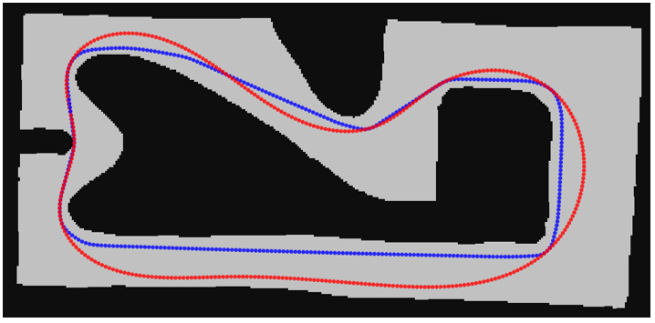
The key performance metric in racing is lap time, and even on the same track the lap time changes dramatically depending on which line you drive. The Centerline extracted from the map is merely the line through the middle of the track — it says nothing about how to get through it quickly. To reduce lap time, you either widen the turning radius through corners to lower curvature, or shorten the distance traveled. This post covers how the global trajectory the car actually drives is generated on top of the extracted track data (centerline + left/right widths).
Overview
Once the Centerline and Wall boundary extraction is done, the same node generates two global lines with different characters.
Two global lines
- IQP (minimum curvature, main line): minimizes the curvature of the whole path, taking corners wide and smooth — usually the fastest lap time. This is the line the stack follows as its main raceline.
- SP (shortest path, auxiliary line): minimizes distance traveled, hugging the inner walls — used as a shortcut line for overtaking.
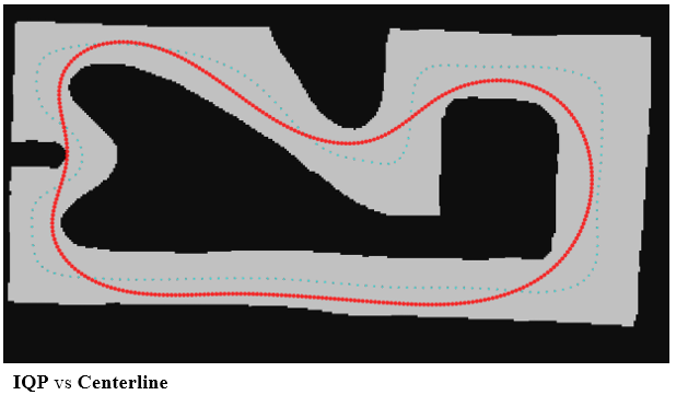 IQP vs. Centerline
Optimization Technique: alpha Parameterization
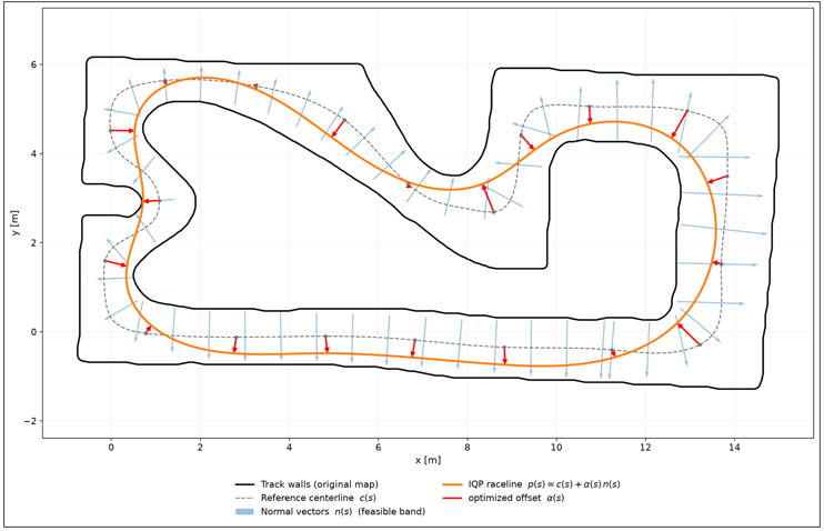
If you handle the path directly in x/y coordinates, the number of optimization variables grows by two per point, and the constraint that the path must stay on the track becomes complicated. To simplify this, the path is expressed with a single displacement $\alpha(s)$ describing how far it deviates in the normal direction at each point of the Centerline.
\[p_{race}(s) = p_{center}(s) + \alpha(s)\, n(s), \quad -w_r \le \alpha \le w_l\]This representation simplifies the optimization in two ways.
- Fewer variables: the optimization variables per point shrink from two $(x, y)$ to a single $\alpha$.
- Simpler constraints: staying on the track becomes a simple inequality constraint keeping $\alpha$ within the left/right widths ($-w_r \le \alpha \le w_l$).
How the Two Lines Are Solved
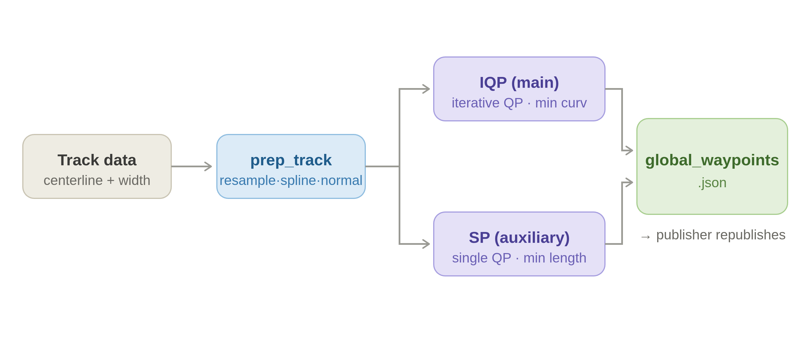
The track data passes through prep_track (resampling, splines, normals) and is then optimized separately into the IQP and SP lines, with both results saved together in global_waypoints.json. The two lines share the same $\alpha$ representation but minimize different objectives.
- IQP (minimum curvature): minimizes the sum of squared curvatures over the whole path.
- The curvature term is nonlinear in $\alpha$, so each iteration linearizes around the current solution and solves a QP, repeatedly (Iterative QP).
- SP (shortest path): minimizes the sum of squared distances between adjacent points.
- The objective is linear in $\alpha$, so a single QP solve yields the solution.
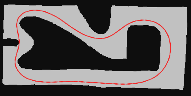 IQP line
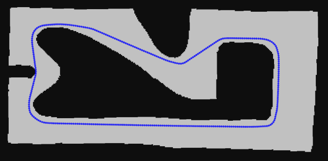 SP line
After optimization, dist_to_bounds recomputes each point’s left/right track widths (d_left/d_right) against the actual walls (the watershed boundary) and stores them alongside.
Adding Speed to the Path (Velocity Profile)
Related code: race_utils/f110_utils/libs/vel_planner/
The IQP/SP optimization decides the shape of the path purely from geometric criteria like curvature or distance, without considering speed. The result only says “where to drive,” not “how fast to drive at each point.” For actual driving, a Velocity Profile assigning a target speed at each point must be layered on top, and this is done in the same node right after the IQP/SP path optimization.
The target speed at each point cannot be chosen arbitrarily — it is bounded by what the vehicle can physically do. There are two main limits.
- Corners (friction circle): higher curvature demands more lateral acceleration, so the achievable speed within the tire grip limit drops.
ggv.csv: friction-circle data with lateral/longitudinal acceleration limits per speed
- Accel/decel (engine): determines when to start braking on a straight and where to accelerate again, with separate limits for acceleration and deceleration.
ax_max_machines.csv: maximum acceleration limit per speedb_ax_max_machines.csv: maximum deceleration (braking) limit per speed
Applying the friction-circle limit to each point’s curvature sets the corner speeds; layering the engine’s accel/decel limits then connects the braking and acceleration segments, completing the velocity profile for the whole path. The details of how the profile is computed are covered in the separate Velocity Planner post.
The three files above live under
stack_master/config/<racecar_version>/veh_dyn_info/; simulation uses theSIMfolder and the real car usesCAR. The same files are also used later for Velocity Planner tuning.
Once the velocity profile is computed, each waypoint is saved to global_waypoints.json with the following fields: position (x_m, y_m), arc length and lateral displacement (s_m, d_m), left/right widths (d_right, d_left), heading and curvature (psi_rad, kappa_radpm), and the velocity profile (vx_mps, ax_mps2).
1
[id, s_m, d_m, x_m, y_m, d_right, d_left, psi_rad, kappa_radpm, vx_mps, ax_mps2]
Integrating the speed over the whole track yields the estimated lap time (Estimated laptime in the log). On map f, IQP comes out at 17.12 s and SP at 19.77 s — even though SP travels a shorter distance, its higher corner curvature forces lower speeds, giving a slower lap.
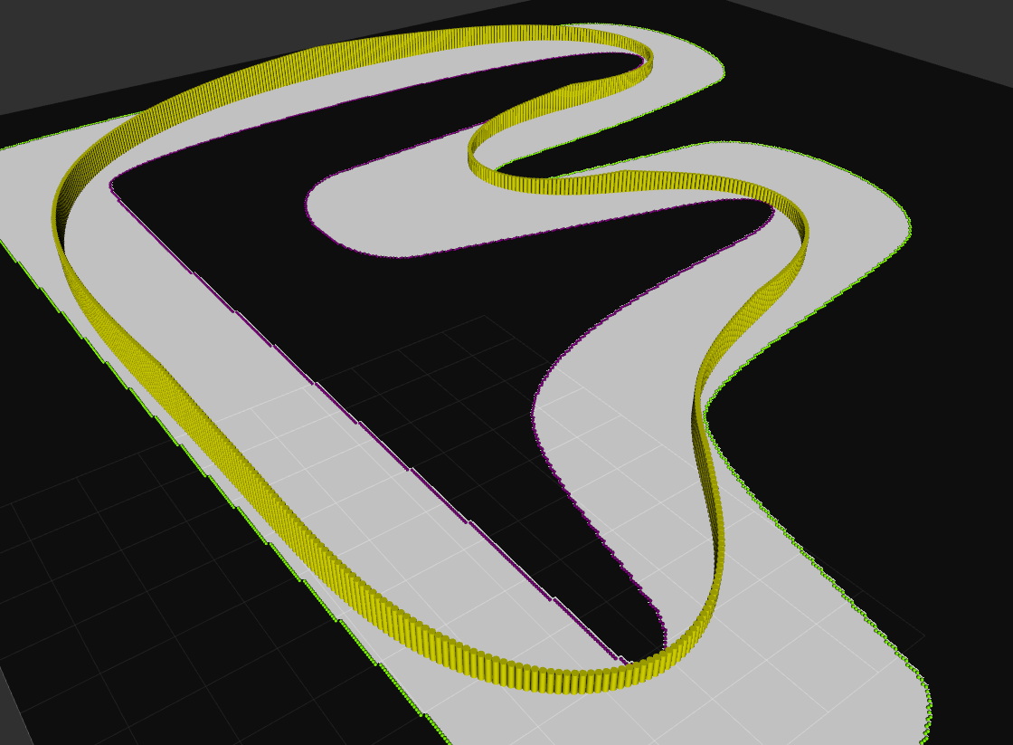 IQP raceline with velocity markers and Wall boundary (RViz 3D)
The height of the yellow markers in the figure is the longitudinal speed (vx). The markers are lowest at corner apexes, and you can see the car braking ahead of corner entry and accelerating again on corner exit.
The closer ggv.csv is to measured values, the more realistic the accel/decel profile becomes — but rather than keeping the file at measured values, the UNICORN Racing team treats it as a key tuning parameter and adjusts it actively.
Running It (UNICORN Racing Stack)
The IQP/SP optimization runs in the same node right after the Centerline/Wall boundary extraction, so raceline_generator.launch.xml runs everything from extraction to optimization at once.
1
2
3
4
5
ros2 launch stack_master raceline_generator.launch.xml map:=f sim:=true
# map:=map name
# On the real car use sim:=false (CAR config) / reverse:=true / show_plots:=true
# With enable_mintime:=true the main line is optimized for minimum time (mintime) instead of minimum curvature
# → maps/f/global_waypoints.json (IQP main + SP auxiliary)
By default it optimizes with minimum curvature (mincurv_iqp), but turning on the enable_mintime argument switches to the minimum-time optimization that accounts for vehicle dynamics (Mintime Optimization).
Execution Results
Running with map:=f performs the IQP/SP optimization right after the Centerline/Wall boundary extraction, printing logs like the ones below. The main IQP line is computed first, followed by the auxiliary SP line.
1
2
3
4
5
[GB Planner]: Start Global Trajectory optimization (mincurv_iqp)...
[GB Planner]: Lap Completed now publishing global waypoints
[GB Planner]: Start reverse Global Trajectory optimization with shortest path...
[GB Planner]: Done with shortest path optimization
[GB Planner]: Lap Completed now publishing shortest path global waypoints
The accompanying summary contains each line’s estimated lap time and top speed. For example, on map f it prints IQP estimated lap time: 10.5857s; IQP maximum speed: 6.6802m/s; SP estimated lap time: 14.8311s; SP maximum speed: 9.6614m/s, showing the IQP lap time is shorter.
Checking the IQP Line
The optimized main raceline (orange) is plotted together with the Wall boundary, Centerline, and car width. You can check that it sweeps corners wide to lower curvature, and that the car width (including the safety width) stays inside the walls.
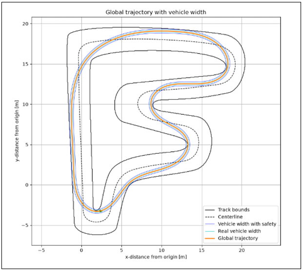 IQP trajectory and car width
Orange is the IQP raceline, the dashed line is the Centerline, the outer solid lines are the Wall boundary, and the two inner lines are the car width (actual/safety). safety_width is the effective width the optimization tries to secure — the actual vehicle width plus a safety margin. Increasing it makes the line keep a larger margin from the walls.
If
safety_widthgrows beyond the track width, no feasible path remains for the car, the optimization fails, and the node exits. When adjusting the value, increase it gradually within what the track width allows.
Checking the SP Line
Unlike IQP, SP keeps the line as straight as possible and minimizes the total path length.
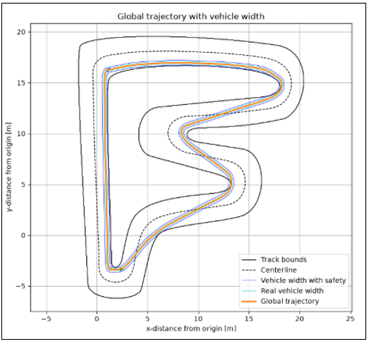 SP trajectory and car width
Assigning Sectors
Right after optimization, sector_slicer and ot_sector_slicer run so the track can be divided into sectors. Move the S position with the slider, mark boundary points with Select S (normal sectors) and Select Overtaking S (overtaking sectors), then save with Done.
The overtaking-sector window shows IQP (red), SP (blue), and the boundary (green) together, so you can set the boundaries while seeing which segments favor overtaking (straights, wide corners). The results are saved as
speed_scaling.yamlandot_sectors.yaml.
Artifacts
The results saved under maps/f/ are:
global_waypoints.json: IQP line, SP line, Centerline, Wall boundary, estimated lap timesspeed_scaling.yaml·ot_sectors.yaml: sector assignment results
Key Parameters: global_planner_params.yaml
Most of the IQP/SP optimization behavior is adjusted through the parameters in stack_master/config/global_planner_params.yaml, which are passed to the node via the launch file.
1
2
3
4
5
6
7
# stack_master/config/global_planner_params.yaml
global_planner:
  ros__parameters:
    required_laps: 1               # laps to drive before optimization
    safety_width: 1.0              # safety width of the main IQP raceline [m] (incl. car width)
    safety_width_sp: 1.0           # safety width of the SP shortcut line [m]
    occupancy_grid_threshold: 10   # free-space threshold (map binarization)
reverse_mapping, which reverses the raceline direction, is passed as a launch argument (reverse:=true).
Each parameter affects the optimization as follows.
| Parameter | Role | Increase / Decrease |
|---|---|---|
safety_width | Effective width = car width + safety margin; the track width is narrowed by this amount in the alpha constraints | Increasing keeps the line further from walls (safer) but shrinks corner radii and increases lap time (fails if it exceeds the track width) / decreasing lets the line approach the walls |
safety_width_sp | Effective width for the SP shortcut line. Same vehicle, so set it equal to safety_width | Same as above, applied to the SP line only |
reverse_mapping | Reverses the raceline’s s direction | Set true when the direction comes out reversed |
If the line hugs corners too closely or the Minimum distance to boundaries warning in the log gets too small, the collision risk with walls rises — raise safety_width gradually and re-optimize. But if you raise it too much at once, no feasible path remains, the optimization fails, and the node exits, so adjust in small steps within what the track width allows. Conversely, if the line is too conservative, lowering safety_width slightly yields a line closer to the corners and a lower lap time.
(Optional) Manual Raceline Editing
Related launch: raceline_tuner.launch.xml
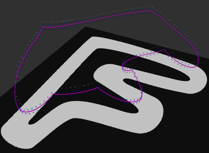 RViz interactive tuner view
raceline_tuner.launch.xml is a node you can use when you want to change the optimized path only in specific segments. It edits the path and speeds interactively — moving a corner line, lowering the speed in a segment, smoothing out jagged parts, and so on. The launch runs the track tuner together with a map publisher for the RViz background and the sector slicers (speed_scaling / ot_sectors) all at once.
The UNICORN Racing team uses a velocity planner based on the friction ellipse and curvature, so this node is rarely used.
These components are bundled together because the pipeline depends heavily on global_waypoints.json. Once the tuner modifies the trajectory, the speed_scaling.yaml and ot_sectors.yaml computed against the old trajectory are no longer valid — so the sector slicer running alongside recomputes the sectors at save time.
Running
1
2
3
ros2 launch stack_master raceline_tuner.launch.xml map:=f
# Runs the tuner + map publisher + sector slicer + RViz all at once.
# The log should show "Initialize NNN waypoints as interactive markers".
1
2
3
[INFO] READ_GLOBAL_WAYPOINTS: Reading global waypoints from .../maps/f/global_waypoints.json
[global_traj_tuner_node]: Reading parameters from f
[global_traj_tuner_node]: Initialize 762 waypoints as interactive markers.
Caution: the tuner publishes
/global_waypoints, and the driving stack (race.launch.xml/base_system.launch.xml) uses the same topic. Running both stacks at once can cause them to fight over the topic — be aware of this, shut down any running driving launch first, and runraceline_tuner.launch.xmlalone.
The RViz View
RViz starts with a dedicated config (raceline_tuner.rviz), so the editing view appears without any manual setup. Speed is represented by marker height (z), so keep the view in Orbit (3D); the interactive markers are published under the /track_info_interactive namespace.
The view shows purple spheres (waypoints), vertical drag handles placed at intervals, and speed labels (e.g. v : 6.68).
Controls: Drag, Then Right-Click Menu
Editing works by dragging markers to change position or speed, then applying commands from the right-click menu. Adjust speed by dragging a handle up/down (height corresponds to speed); position and segment-level commands run from the right-click menu.
| Menu | Action |
|---|---|
| pose_smooth ▸ 10/20/30/idx | Smooth positions around the right-clicked point with a cubic spline (psi/kappa/left-right widths recomputed automatically) |
| vel_smooth ▸ 10/20/30/idx | Smooth speeds (idx = direct input) |
| Anchor1 / Anchor2 | Set segment start/end anchors (the commands below apply between the two anchors) |
| Pos_Straighten | Straighten positions between the two anchors |
| Vel_Straighten | Linearly interpolate speeds between the two anchors |
| Vel_Set | Set the speed between the two anchors to a popup input value |
| entire_translation / entire_rotation | Translate / rotate the entire path |
| int_idx | Change the handle/label display interval (sampling_step) |
| Control-Z | Undo (up to 5 steps) |
| Update | Publish the edited version to /global_waypoints (for checking, without saving to disk) |
| Save | Publish the edited version and save it to global_waypoints.json. The sector slicer running alongside receives it and recomputes/saves speed_scaling.yaml and ot_sectors.yaml |
Example: Raising the Speed in a Segment
- Drag the blue arrow to raise the speed at that point.
- Right-click the waypoint and select vel_smooth.
- Choose the smoothing parameter.
- The velocity profile around the waypoint becomes smooth.
- If you are happy with the result, right-click → Save (or Update to just check).
Edits only reach the disk when you press Save — otherwise they are lost when the node exits. Pressing Save writes the modified trajectory to
global_waypoints.jsonand simultaneously feeds the updated/global_waypointsto the sector slicer running alongside, so the sectors are recut to match the new trajectory. It is safest to back up the existing line before editing (cp maps/f/global_waypoints.json maps/f/global_waypoints.json.bak)./global_waypoints/markers(the yellow raceline) only fills in after Update or Save.
Wrap-up
The full workflow: the extracted track data passes through prep_track, is optimized into the IQP and SP lines, gets its left/right widths from dist_to_bounds, and is saved as global_waypoints.json. When needed, manual tuning can correct specific segments.
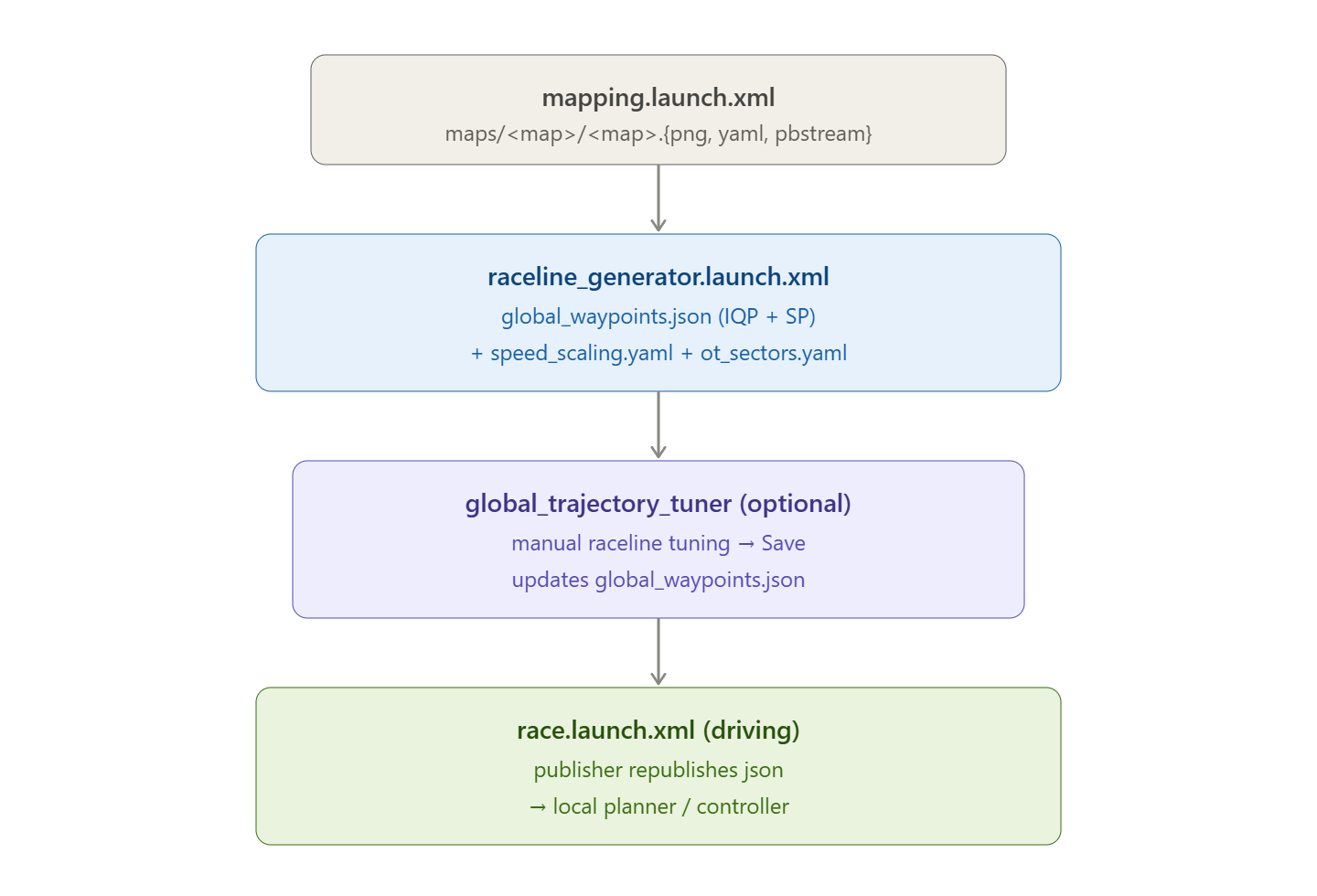 Full workflow (mapping → raceline_generator → raceline_tuner (optional) → race)
At runtime, the resulting global_waypoints.json is republished as the global waypoints topic through global_trajectory_publisher, and during driving it is passed to the state machine and the planners, serving as the central path of the race.