Circuit Design & Wiring Guide: Notes and Improvements
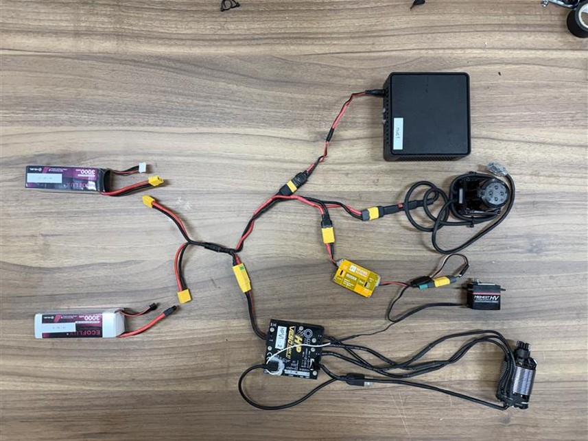
Design notes for wiring
The UNICORN Racing vehicle uses a parallel wiring layout based on XT connectors.
Devices that can take 4S LiPo voltage directly (VESC, LiDAR, NUC) are wired in parallel with XT connectors. Devices that cannot (servo motor) use a Matek BEC to step down the voltage.
Key considerations when building the circuit are below.
Parallel battery wiring
We wired the batteries in parallel so the system remains powered even when swapping batteries.
Wire selection
- Estimate the current draw of each device and choose wires that meet the required current capacity.
- A lower AWG number means thicker wire and lower resistance. For safety, we recommend selecting one size lower than the minimum required AWG.
- For example, VESC power lines typically draw 20–60A during normal driving and up to 80–120A during hard acceleration. Using 12 AWG silicone wire is sufficient without excessive heating.
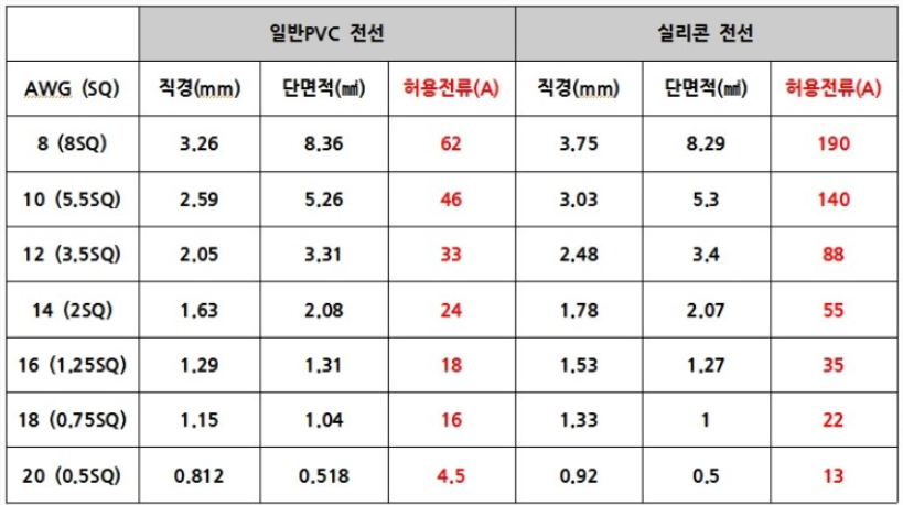
- PVC and silicone wires are distinguished by their conductor structure and insulation material.
Connector selection
- We use Amass XT series connectors (XT30, XT60, XT90) for easy connection and removal.
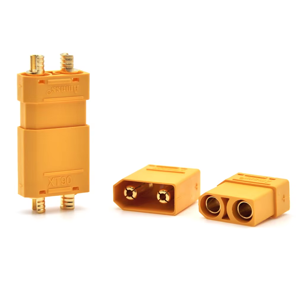
- Connector characteristics are summarized below.
| Item | XT30 | XT60 | XT90 |
|---|---|---|---|
| Rated current (continuous) | 15A | 30A | 40A |
| Max current | 20A | 60A | 90A |
| Recommended wire AWG | 24–18 AWG | 16–14 AWG | 12–10 AWG |
- Verify the expected current for each wire/connector pair and select the appropriate connector.
- XT60 can be used with 12 AWG wire, but soldering can be difficult due to the thick wire.
- Names of special connectors (NUC power, VESC PPM / SENCE port):
- NUC power connector: barrel jack (inner/outer diameter varies)
- VESC port connector: JST-PH (3-pin, 6-pin, …) housing + JST-PH crimp connector
Finished wiring layout
The basic circuit layout is shown below.
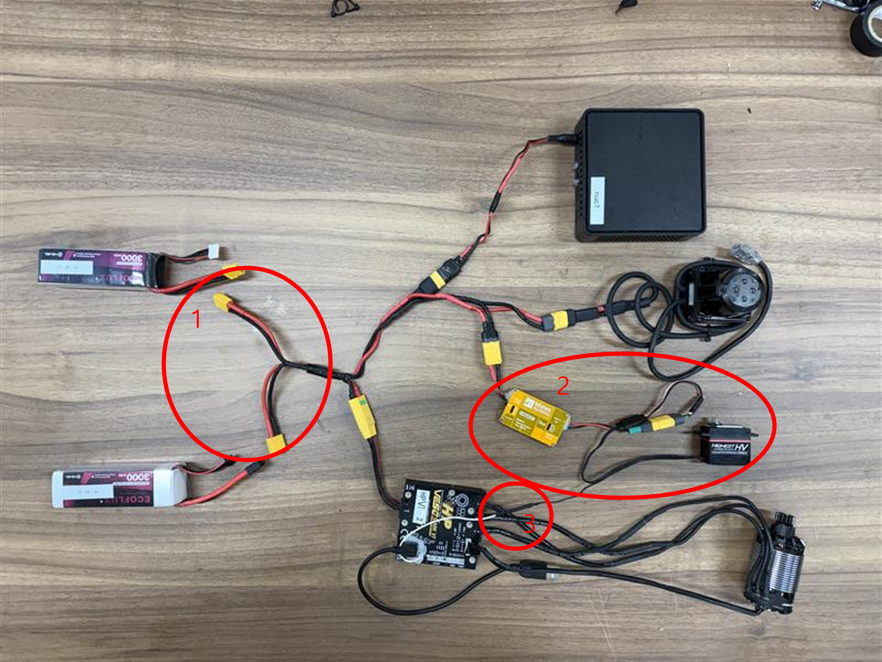
Applied on the vehicle
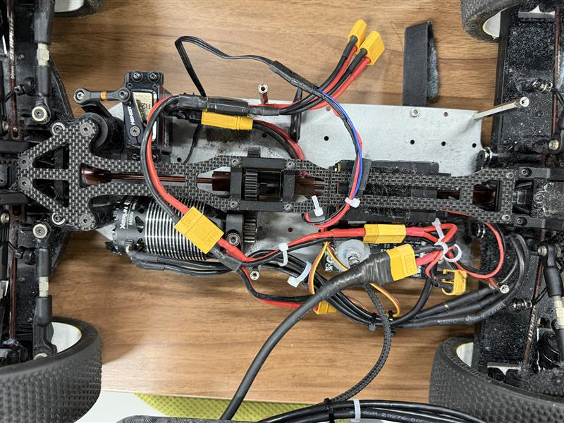
Below is the actual vehicle wiring based on the layout above.
Improvements to the design
The current approach branches every wire in parallel, which lets us complete wiring without additional boards. However, it makes fault isolation difficult during competitions when hardware issues occur.
To address this, we plan to design and add a dedicated power distribution PCB.