Chassis and Top Plate Assembly Guide
Parts Preparation
Empty SRX8 chassis.
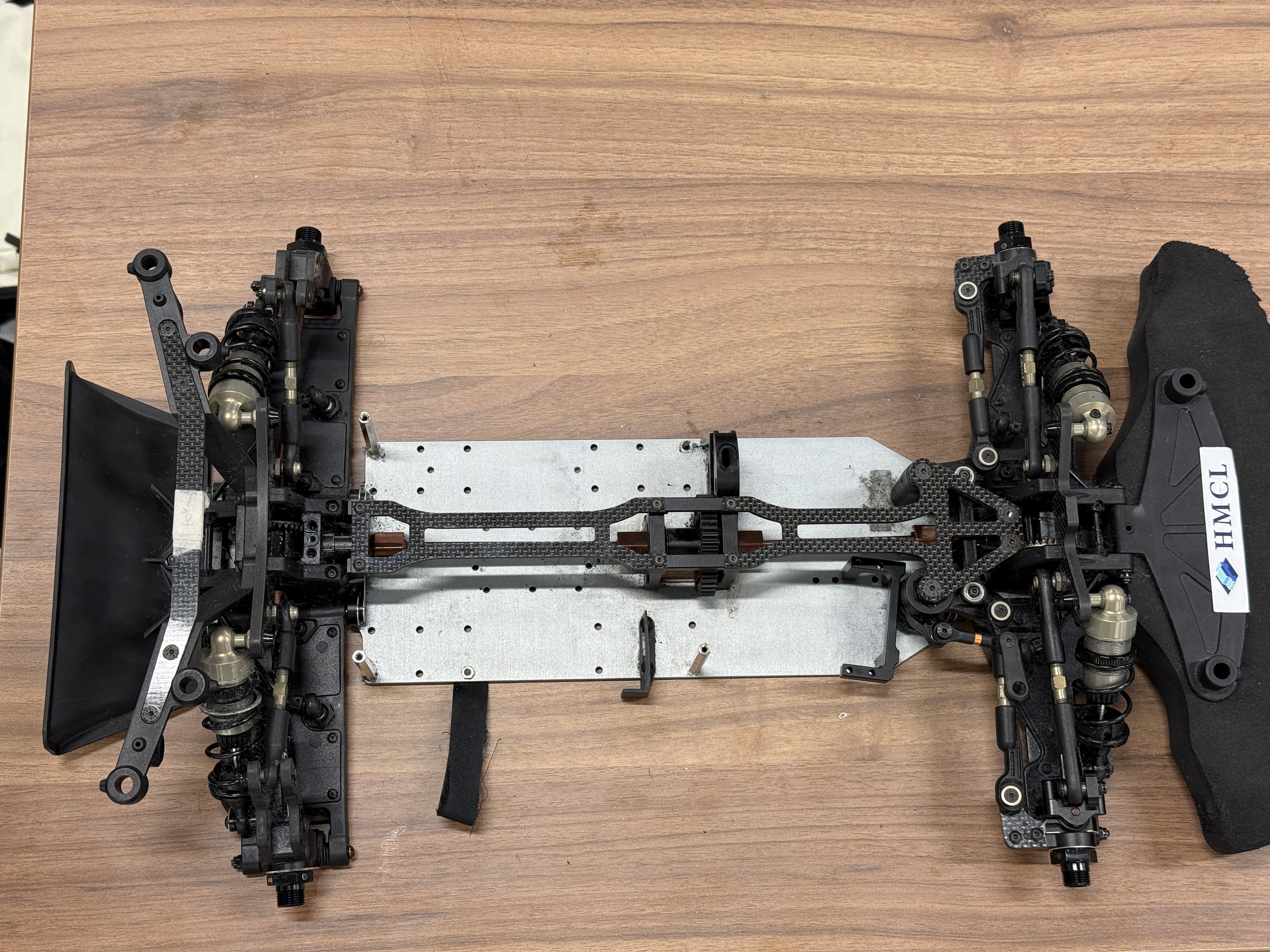 Empty SRX8 chassis
All components needed for one car.
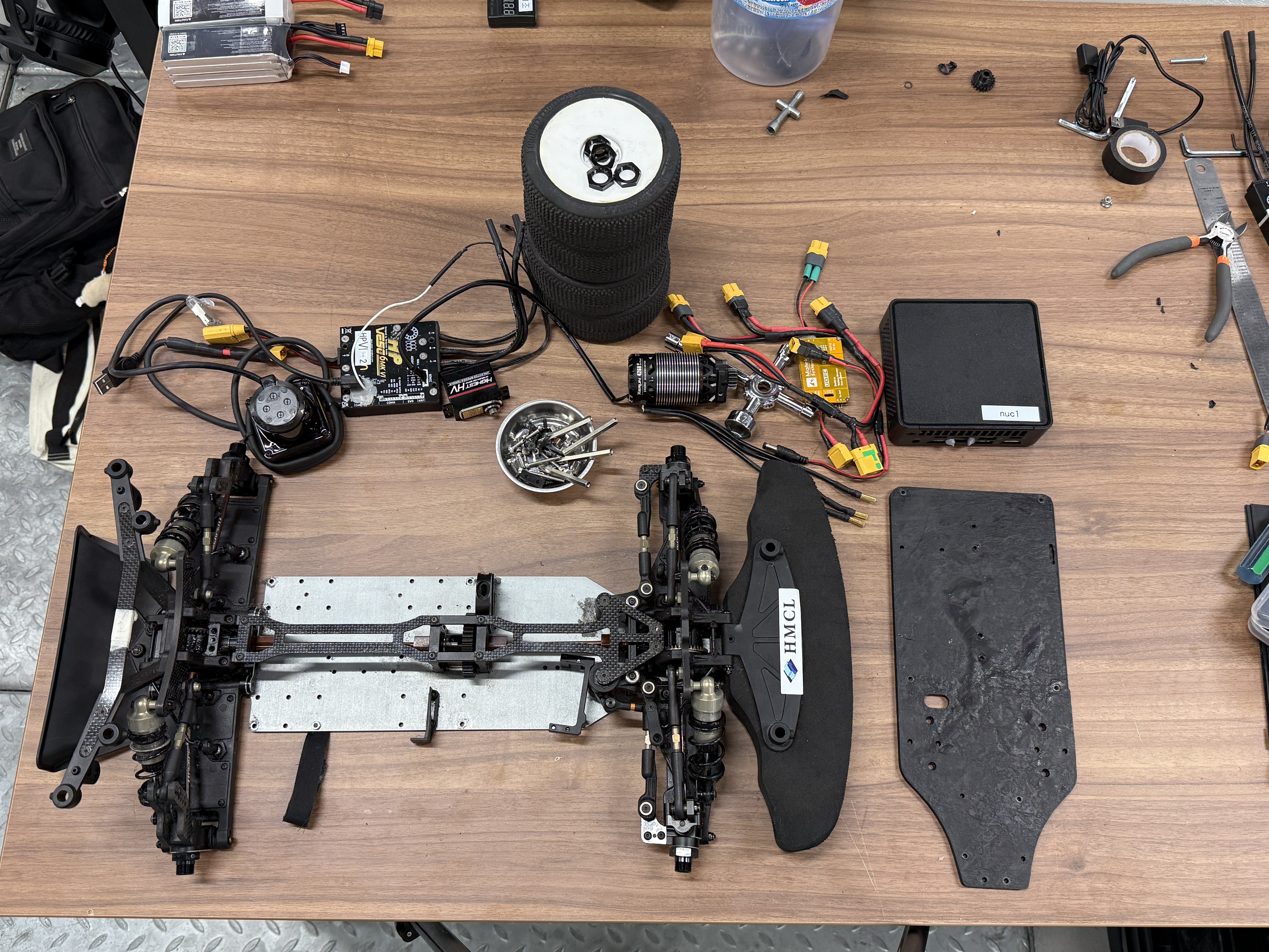 Full set of required components
Power harnesses are unified to XT-60.
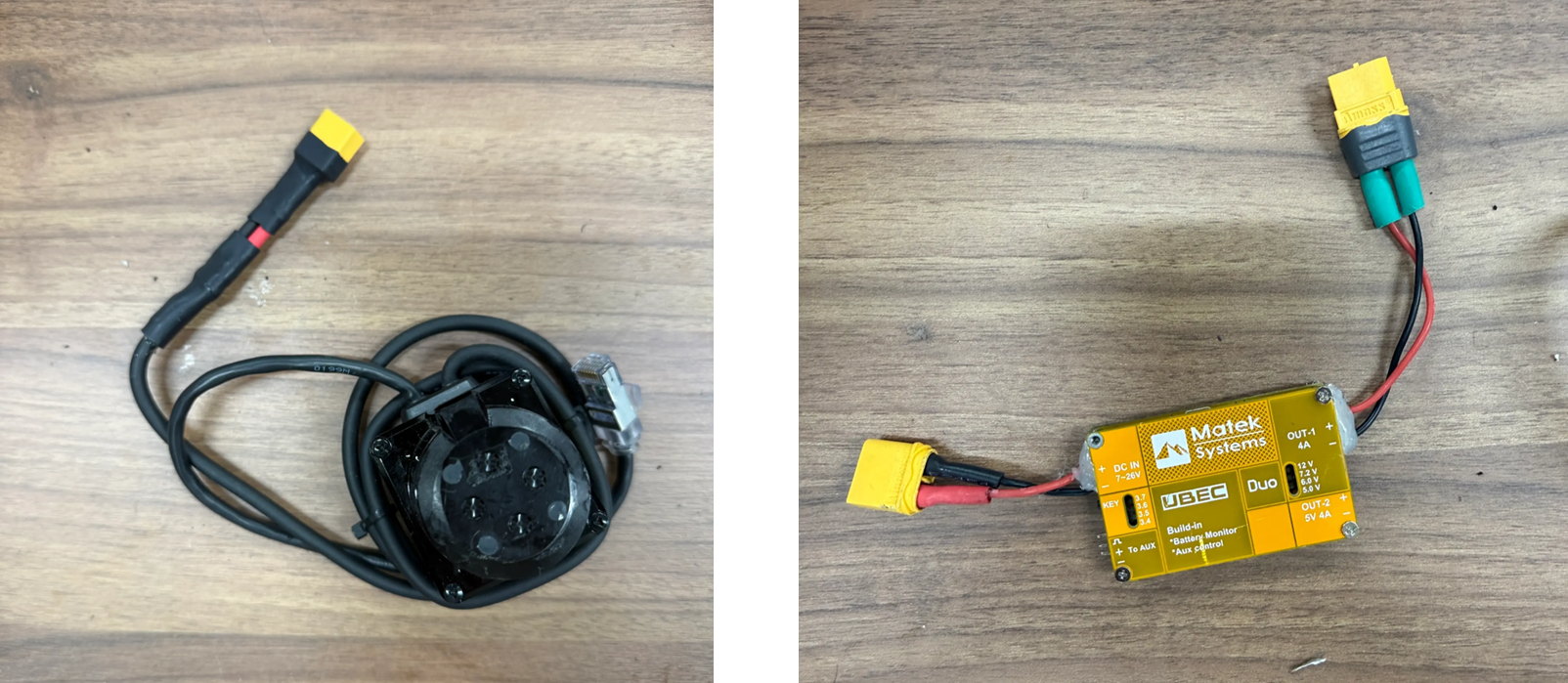
LiDAR and BEC inputs/outputs converted to XT-60
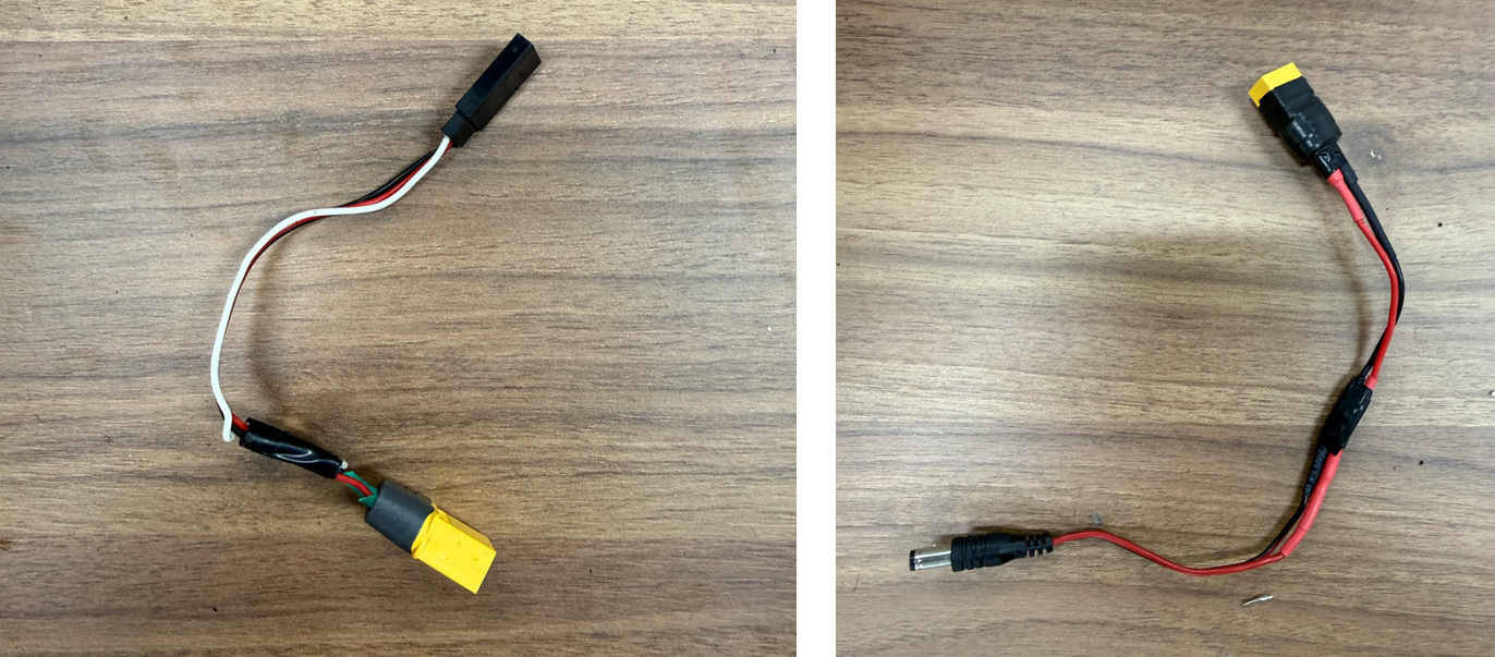
XT-60 adapters for servo 3-pin and NUC barrel jackThe wiring diagram is for understanding only; do not pre-assemble yet.
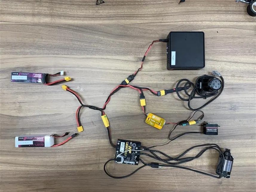 Overall wiring diagram
Lower Plate Assembly
Mounting the VESC
We machined additional holes in the aluminum lower plate for VESC mounting and positioned the VESC using those holes.
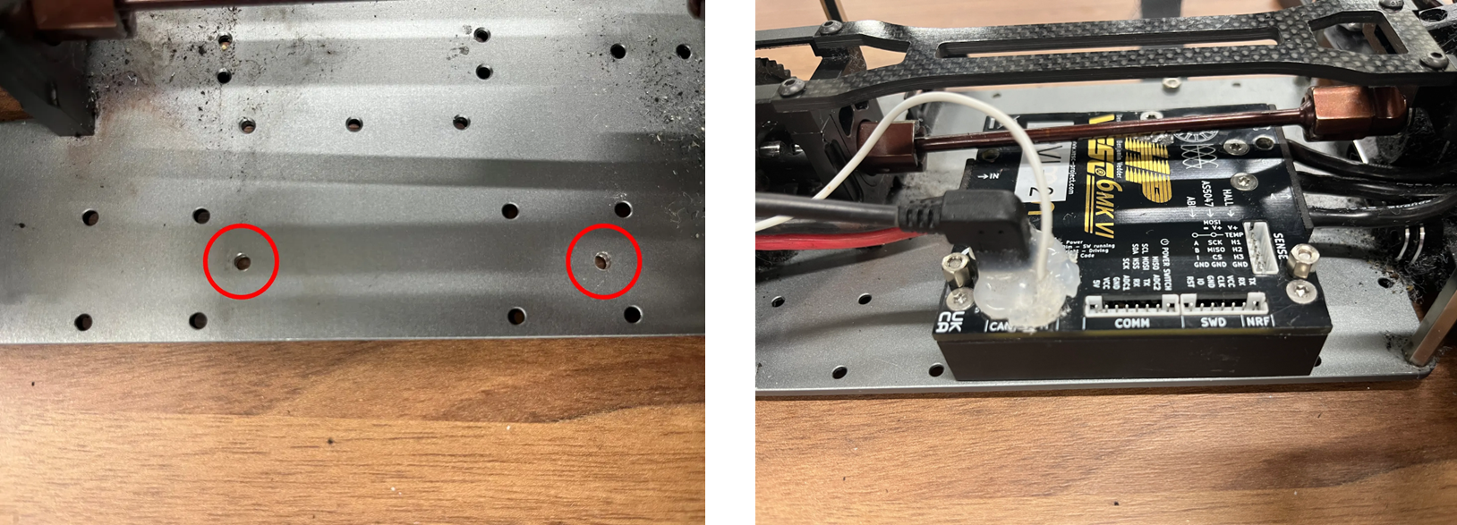 Machined holes for VESC mounting
To prevent the top cover from bending, washers were added so bolts/nuts are not over-tightened.
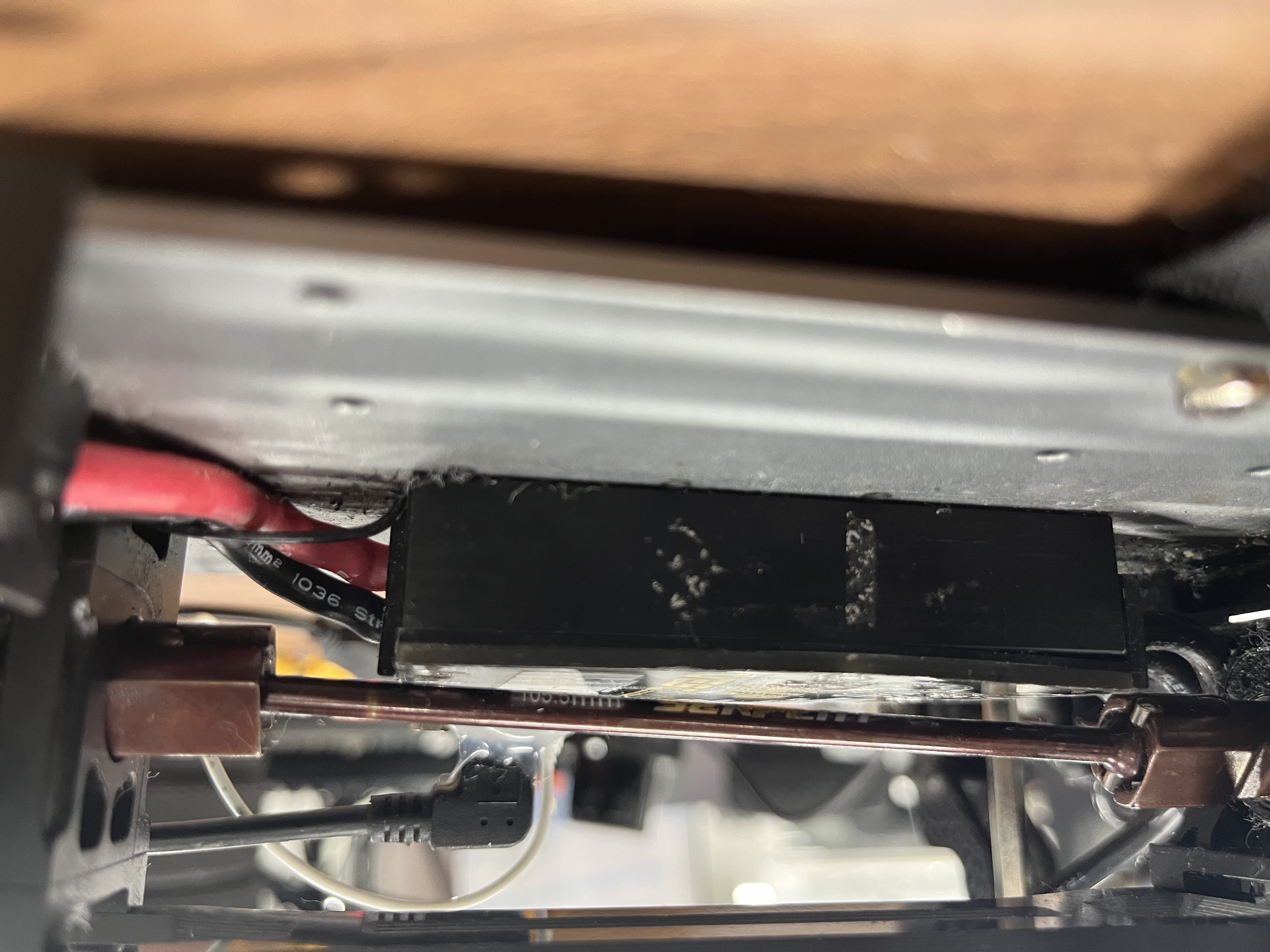 VESC fastened with washers
After mounting, we confirmed the driveshaft travel does not interfere with the VESC.
Battery Velcro Strap Mount
Using existing holes, we fixed a Velcro strap so the battery can be secured later.
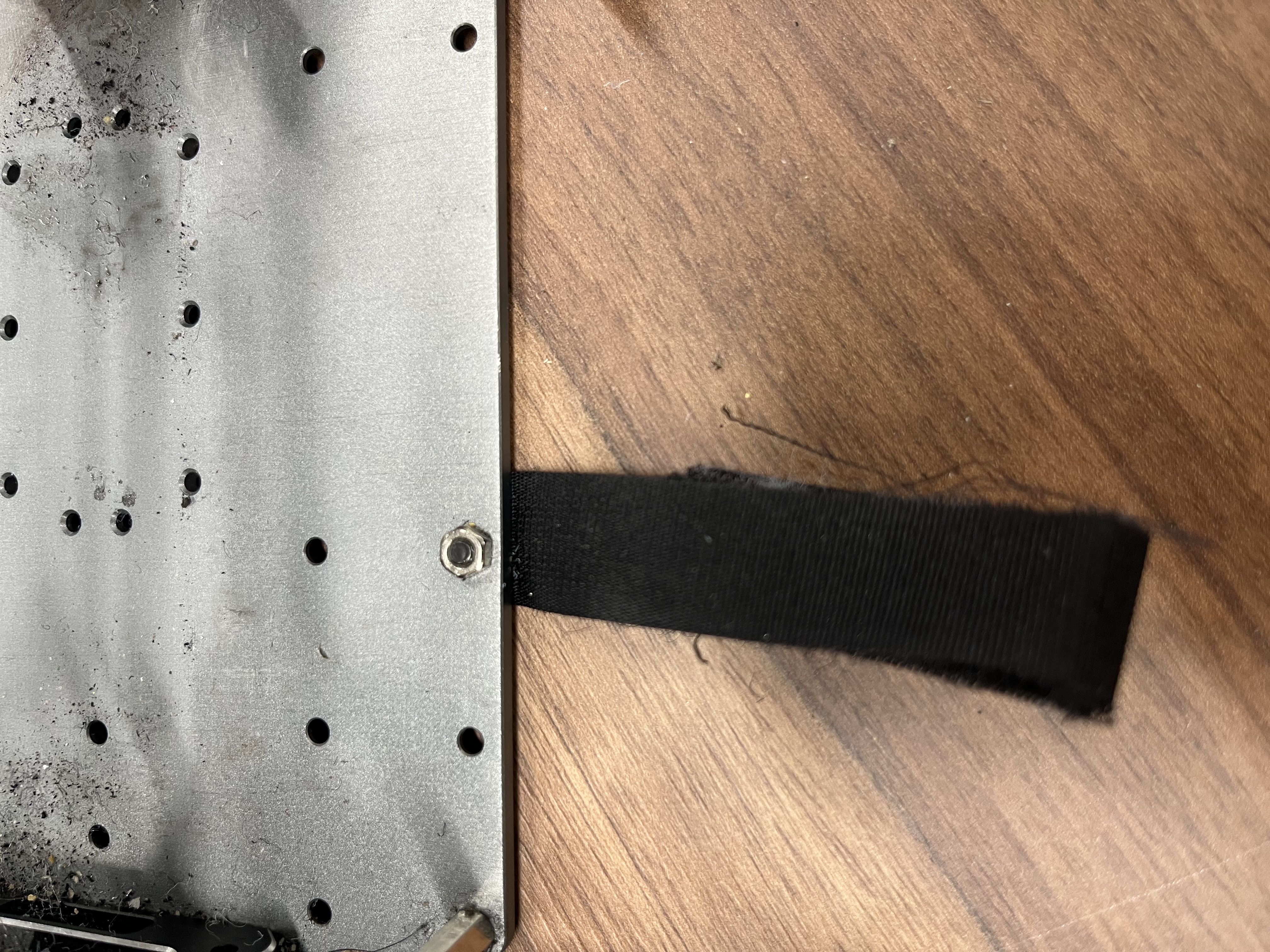 Velcro strap mounted to the lower plate
Mounting the Servo Motor
A support piece removes the height gap, and the servo cable is routed inward.
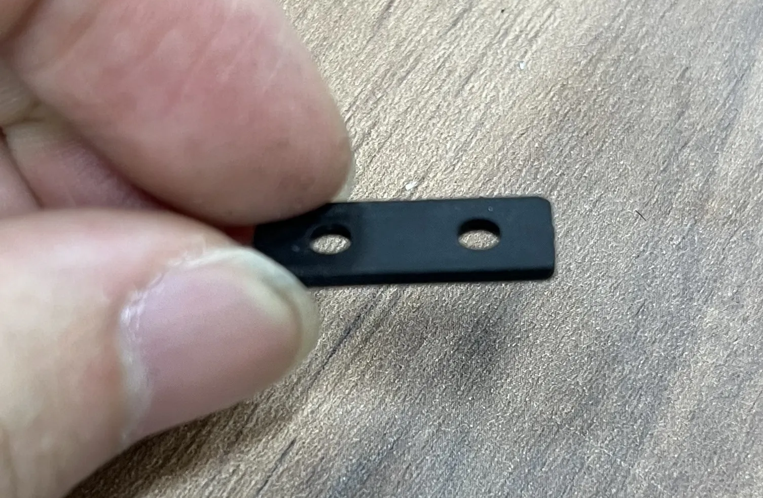
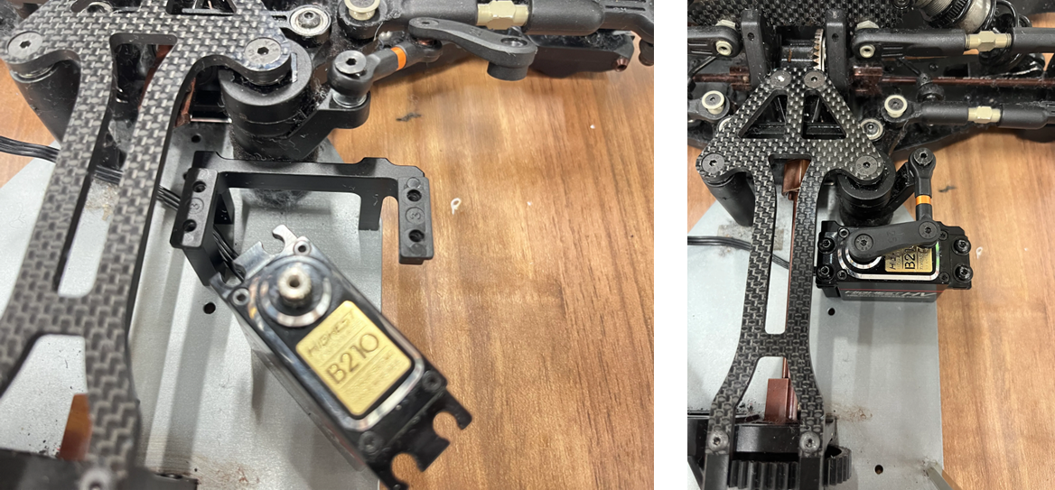 Servo support and mounting example
Center the servo first, then attach the horn. See /unicorn-racing/posts/servo-horn-after-alignment/ for details.
Motor Installation
Mount the DC motor after setting the gap between the pinion gear and the drivetrain gear.
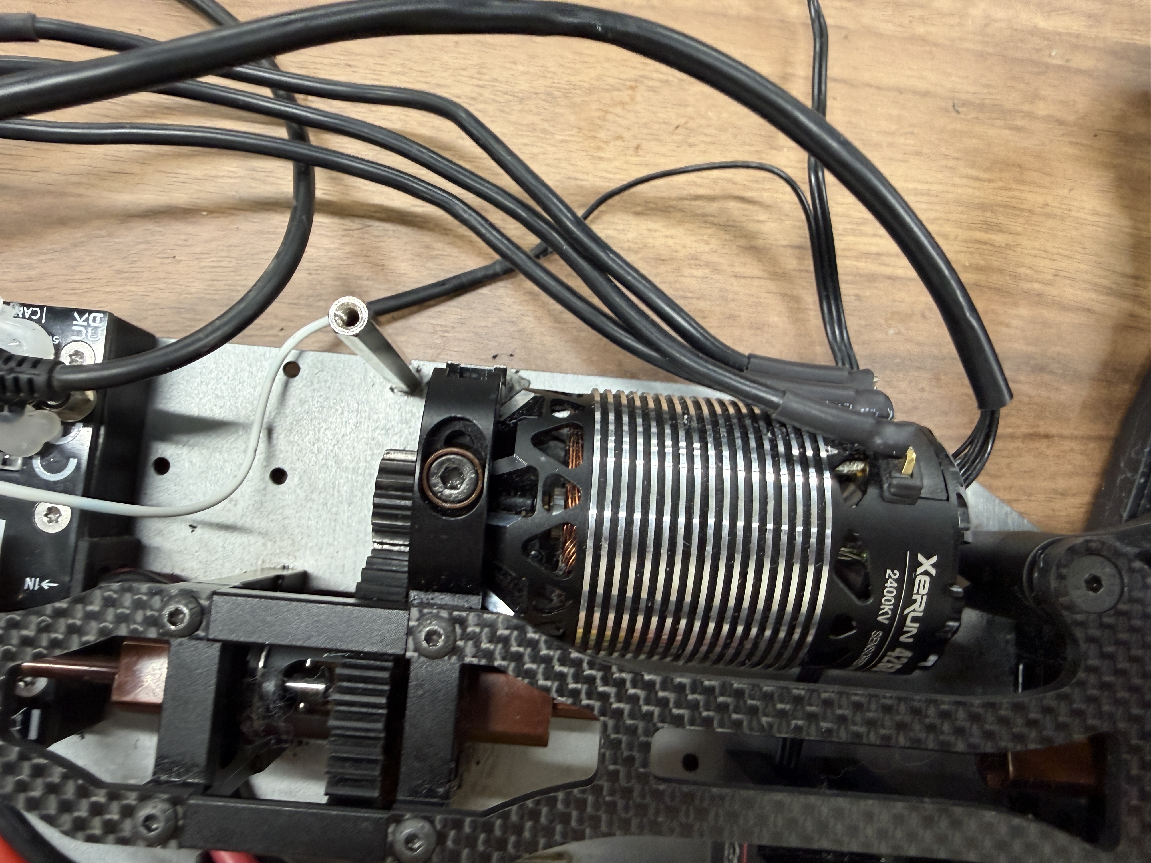 Pinion-to-driveshaft gear gap
Gap adjustment steps: /unicorn-racing/posts/motor-pinion-gear-gap-adjustment/.
Standoff Nuts
Once the lower assembly is done, install standoff nuts to support the top plate.
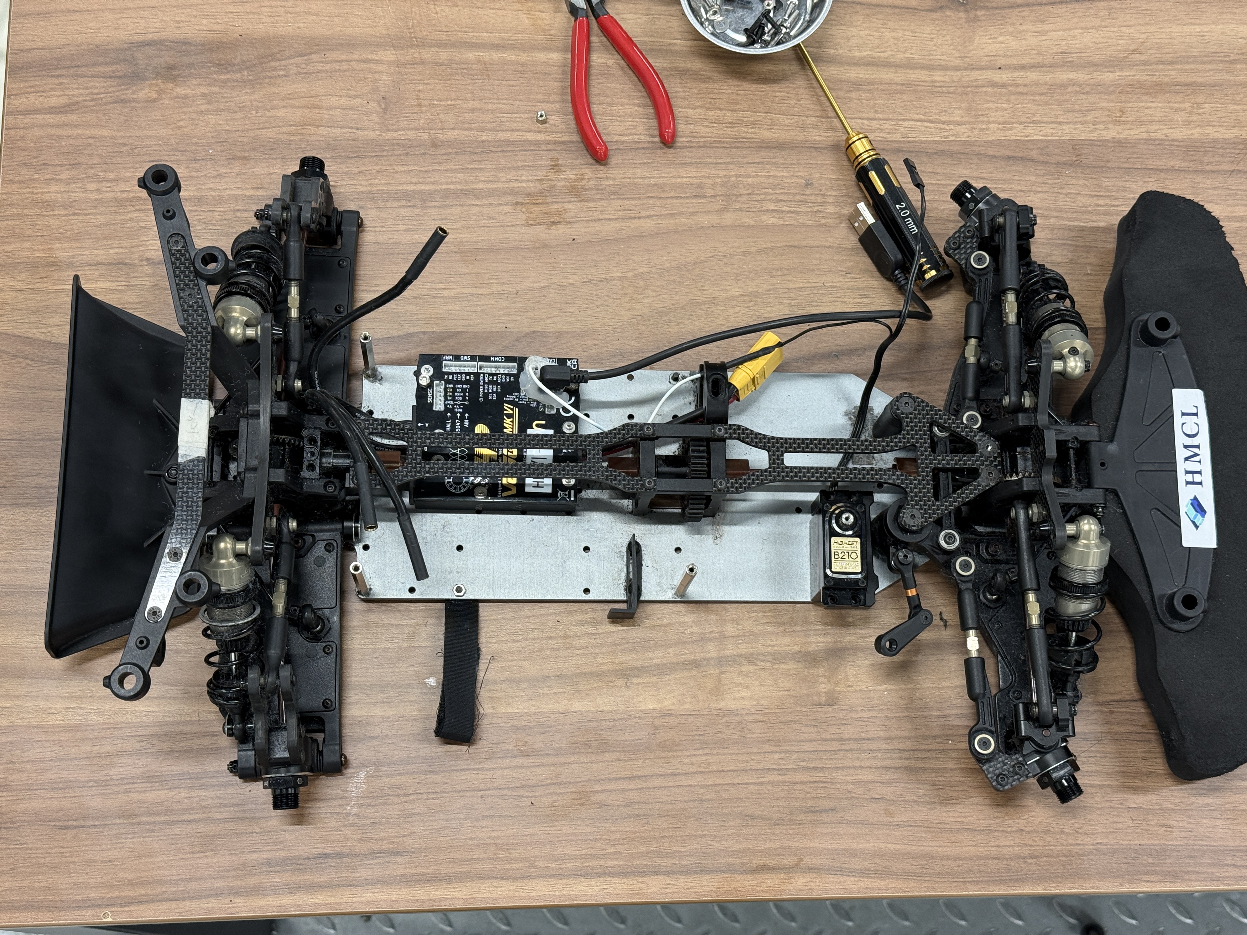 Standoff nuts installed
Top Plate Assembly
Mounting the IMU
Attach the IMU to the underside of the top plate first.
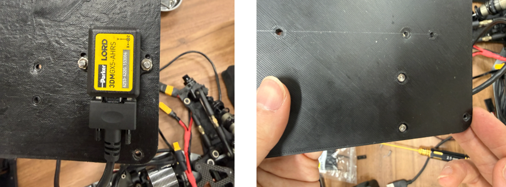 IMU mounted under the top plate
Mounting the NUC
Align the NUC with the two mounting holes and use a nut/washer stack to prevent the bottom from lifting.
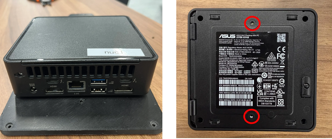 NUC mounting with nut/washer stack
Mounting the LiDAR
Finally, secure the LiDAR on the top plate.
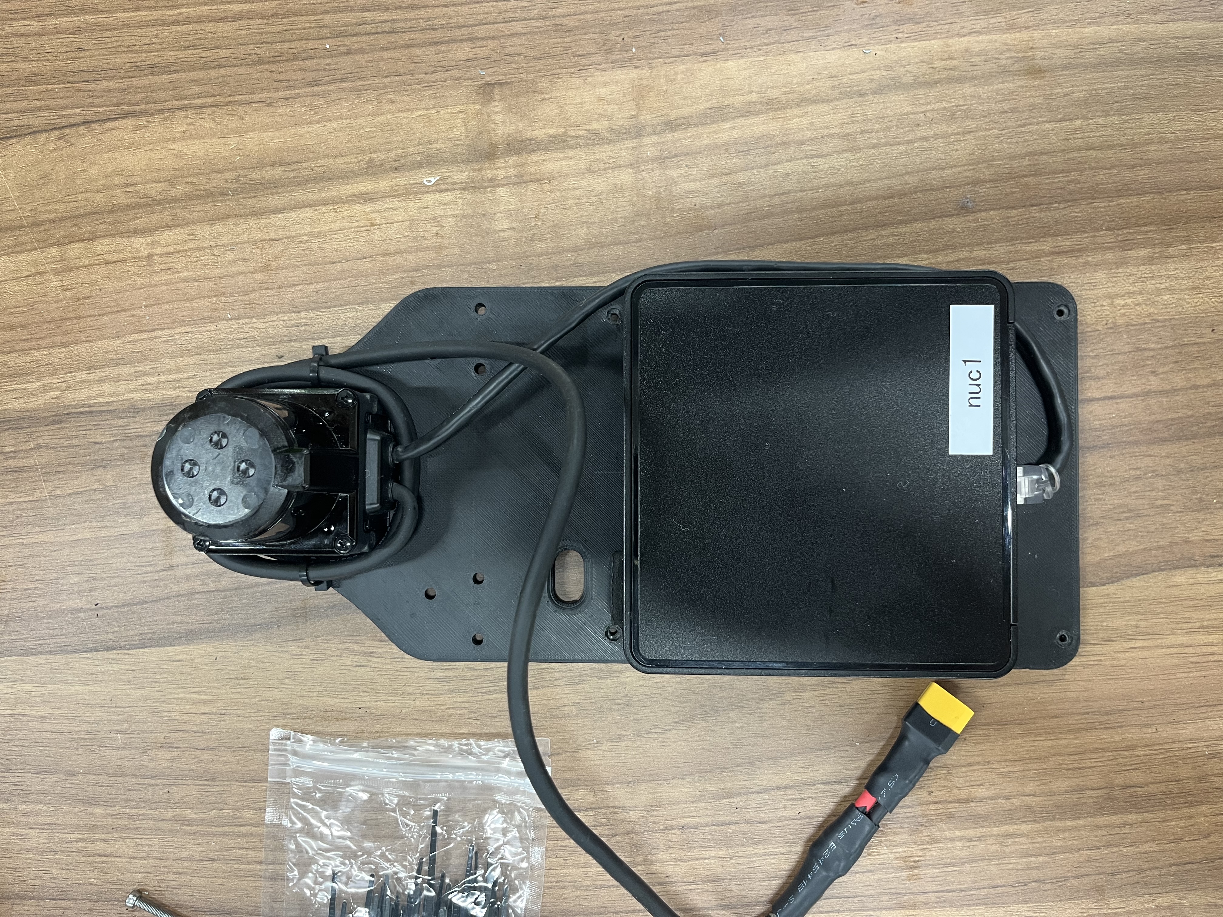 LiDAR mounted on the top plate
Wrap-up
Standardizing power connectors, checking mechanical interference, and setting proper clamping force are all critical for this assembly. Washers protected the VESC housing, and precise alignment/gaps were set for the servo and motor before tightening. After standoffs and top plate installation, finish with tidy cable management to prevent vibration or disconnection during driving.