Sensor TF Setup Guide Based on base_link
Introduction
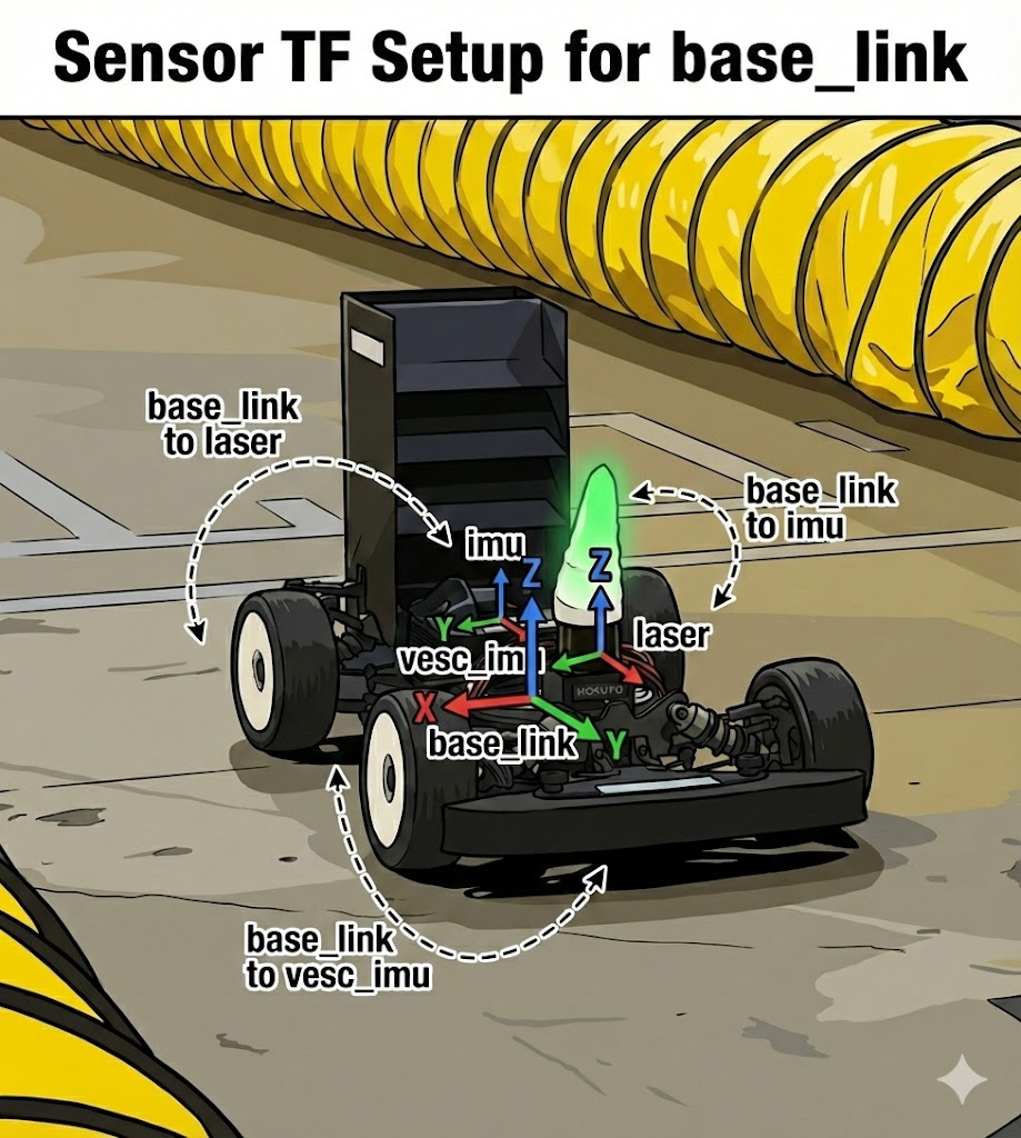
One of the first problems you hit when building a robot is sensor frame alignment. To fuse data from LiDAR, IMU, and cameras, the system must know exactly where each sensor is mounted on the robot.
This guide explains how the Roboracer platform (SRX1 vehicle) uses ROS TF (Transform) to define sensor coordinate frames.
What is TF (Transform)?
In ROS, TF manages the transformation relationships between different coordinate frames.
For example:
- LiDAR is 30 cm away from the robot center (
base_link). - IMU is 6 cm to the left of the robot center.
TF defines and manages these spatial relationships.
Why do we need TF?
Each sensor publishes data in its own frame:
- LiDAR measures obstacles in the
laserframe. - IMU publishes acceleration/gyro data in the
imuframe. - Cameras capture images in the
camera_linkframe.
To fuse them, data must be transformed into a common frame. TF provides the position and orientation for those transforms.
UNICORN SRX1 TF Structure
Frame hierarchy
1
2
3
4
5
6
7
8
9
10
11
12
map
`- odom (or carto_odom)
   `- base_link <- robot center frame
      |- imu (Microstrain IMU)
      |  `- imu_rot (rotation correction)
      |- laser (Hokuyo LiDAR)
      |- vesc_imu (VESC IMU)
      |  `- vesc_imu_rot
      `- chassis (chassis)
         `- zed_camera_link (ZED camera)
            |- camera_link (left lens)
            `- zed_camera_right_link (right lens)
Frame summary
| Frame | Description | Parent |
|---|---|---|
| map | Global fixed frame (SLAM map) | - |
| odom | Odometry frame (with drift) | map |
| base_link | Robot center (rear axle center, ground) | odom |
| imu | IMU sensor frame | base_link |
| laser | LiDAR sensor frame | base_link |
| vesc_imu | VESC controller IMU | base_link |
| chassis | Chassis (5 cm above base_link) | base_link |
| zed_camera_link | ZED stereo camera | chassis |
Coordinate conventions
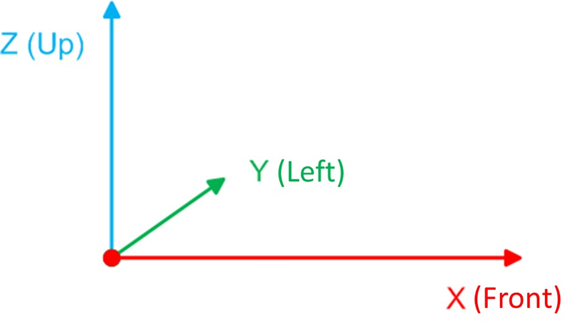
Multiple conventions are used in robotics. UNICORN follows the ROS standard (REP-105).
base_link: FLU (Forward-Left-Up)
- X axis: forward (driving direction)
- Y axis: left (driver’s left)
- Z axis: up
map/odom: ENU (East-North-Up)
- X axis: east
- Y axis: north
- Z axis: up
Why use different conventions?
base_linkis the robot-centered frame for motion control.map/odomare world frames for global positioning.
It is natural to process sensor data in the robot frame and express the final pose in the world frame.
SRX1 sensor placement
Let’s look at where each sensor is mounted on SRX1.
Sensor positions (relative to base_link)
| Sensor | X (m) | Y (m) | Z (m) | Notes |
|---|---|---|---|---|
| IMU | 0.085 | 0.06 | 0.065 | Front-left offset |
| LiDAR | 0.270 | 0.0 | 0.127 | Centerline, front |
| VESC IMU | 0.10 | 0.0 | 0.127 | VESC controller |
| ZED Camera | 0.390 | 0.0 | 0.09 | Front-most, center |
1
2
3
4
5
6
7
8
9
Front
        ^
    [LiDAR]  (0.27, 0, 0.127)
        |
     [IMU]   (0.085, 0.06, 0.065) <- 6cm left
        |
    [VESC]   (0.10, 0, 0.127)
        |
    base_link (0, 0, 0)
Placement details
The Microstrain IMU cannot be mounted exactly at the center, so it is offset 6 cm to the left. TF automatically compensates for this offset.
TF configuration file
Sensor TFs for SRX1 are defined in this file:
1
UNICORN/stack_master/config/SRX1/devices/static_transforms.launch.xml
File contents
1
2
3
4
5
6
7
8
9
10
11
12
13
14
15
16
17
18
19
20
21
22
23
24
25
26
27
28
29
<!-- -*- mode: XML -*- -->
<launch>
   <!-- TFs -->
  <arg name="pub_map_to_odom" default="False"/>

  <!-- 1. IMU Transform -->
  <node pkg="tf2_ros" type="static_transform_publisher" name="base_link_to_imu"
        args="0.085 0.06 0.065 0.0 1.0 0.0 0.0 base_link imu" />

  <node pkg="tf2_ros" type="static_transform_publisher" name="imu_to_imu_rot"
        args="0.0 0.0 0.0 0.0 1.0 0.0 0.0 imu imu_rot" />

  <!-- 2. LiDAR Transform -->
  <node pkg="tf2_ros" type="static_transform_publisher" name="base_link_to_laser"
        args="0.270 0.0 0.127 0.0 0.0 0.0 1.0 base_link laser" />

  <!-- 3. VESC IMU Transform -->
  <node pkg="tf2_ros" type="static_transform_publisher" name="base_link_to_vesc_imu"
        args="0.10 0.0 0.127 0.0 0.0 -0.7071 0.7071 base_link vesc_imu" />

  <node pkg="tf2_ros" type="static_transform_publisher" name="vesc_imu_to_vesc_imu_rot"
        args="0.0 0.0 0.0 0.0 0.0 0.7071 0.7071 vesc_imu vesc_imu_rot" />

  <!-- 4. Map to Odom (optional) -->
  <group if="$(arg pub_map_to_odom)">
    <node pkg="tf" type="static_transform_publisher" name="map_to_odom"
          args="0 0 0 0 0 0 map odom 10" />
  </group>
</launch>
Interpreting TF parameters
static_transform_publisher args format
1
args="x y z qx qy qz qw parent_frame child_frame"
- x, y, z: translation (meters)
- qx, qy, qz, qw: rotation (quaternion)
- parent_frame: parent frame
- child_frame: child frame
Example 1: LiDAR transform
1
args="0.270 0.0 0.127 0.0 0.0 0.0 1.0 base_link laser"
- 27 cm forward
- centered left/right
- 12.7 cm up
- rotation: (0, 0, 0, 1) = identity
- transform from
base_linktolaser
This means the LiDAR is 27 cm in front of the robot center and points in the same direction as base_link.
Example 2: IMU transform
1
args="0.085 0.06 0.065 0.0 1.0 0.0 0.0 base_link imu"
- 8.5 cm forward
- 6 cm left
- 6.5 cm up
- rotation: (0, 1, 0, 0) = 180 deg pitch
- transform from
base_linktoimu
This indicates the IMU is left-offset and physically mounted upside down.
1
2
3
4
Normal:    Flipped (180 deg pitch):
  ^ Z         Z  v
  |              |
  o--> X    X <--o
Understanding quaternion rotations
What is a quaternion?
A quaternion represents 3D rotation using four numbers (qx, qy, qz, qw).
Common rotations
| Rotation | Quaternion (qx, qy, qz, qw) | Notes |
|---|---|---|
| None | (0, 0, 0, 1) | Identity |
| Z +90 deg | (0, 0, 0.7071, 0.7071) | Left turn |
| Z -90 deg | (0, 0, -0.7071, 0.7071) | Right turn |
| Y 180 deg | (0, 1, 0, 0) | Flipped |
| X +90 deg | (0.7071, 0, 0, 0.7071) | Roll left |
Why does the IMU rotate 180 deg?
The IMU is physically mounted upside down. TF corrects this so the data can be used normally.
Why is imu_rot needed?
imu_rot is used as the Cartographer tracking_frame. It applies an additional 180 deg rotation to restore the IMU orientation.
1
2
<node pkg="tf2_ros" type="static_transform_publisher" name="imu_to_imu_rot"
      args="0.0 0.0 0.0 0.0 1.0 0.0 0.0 imu imu_rot" />
1
base_link --[180 deg pitch]--> imu --[180 deg pitch]--> imu_rot
As a result, imu_rot aligns with base_link while still passing through the imu frame.
VESC IMU rotation
1
2
3
4
5
<!-- VESC IMU: -90 deg around Z axis -->
args="0.10 0.0 0.127 0.0 0.0 -0.7071 0.7071 base_link vesc_imu"

<!-- VESC IMU rotation: +90 deg around Z axis -->
args="0.0 0.0 0.0 0.0 0.0 0.7071 0.7071 vesc_imu vesc_imu_rot"
Why rotate twice?
The VESC IMU is rotated 90 deg around Z due to the PCB orientation.
vesc_imu: physical mount (-90 deg)vesc_imu_rot: software correction (+90 deg)
1
base_link: X-> Y^     vesc_imu: X^ Y<-     vesc_imu_rot: X-> Y^
Ultimately, vesc_imu_rot aligns with base_link.
TF loading sequence
Launch call order
1
2
3
4
5
6
7
base_system.launch
`- middle_level.launch
   `- low_level.launch  <- TF loaded here
      |- LiDAR driver
      |- IMU driver
      |- VESC driver
      `- static_transforms.launch.xml
low_level.launch
1
2
3
4
5
6
7
8
9
10
11
12
13
14
15
16
17
18
19
20
21
22
23
24
25
26
27
28
29
<!-- UNICORN/stack_master/launch/low_level.launch -->
<launch>
  <arg name="racecar_version" default="$(env CAR_NAME)" />

  <!-- LiDAR -->
  <node pkg="urg_node" type="urg_node" name="laser_node">
    <rosparam file="$(find stack_master)/config/$(arg racecar_version)/devices/lidar.yaml" />
  </node>

  <!-- IMU -->
  <node name="microstrain_inertial_driver" pkg="microstrain_inertial_driver"
        type="microstrain_inertial_driver_node">
    <rosparam file="$(find stack_master)/config/$(arg racecar_version)/devices/imu.yaml" />
  </node>

  <!-- VESC -->
  <group ns="vesc">
    <include file="$(find stack_master)/launch/vesc.launch">
      <arg name="racecar_version" value="$(arg racecar_version)" />
    </include>
  </group>

  <!-- * Static TF load * -->
  <include file="$(find stack_master)/config/$(arg racecar_version)/devices/static_transforms.launch.xml"/>

  <!-- Other nodes -->
  <node pkg="stack_master" type="relay_node.py" name="relay_node" />
  <node pkg="joy" type="joy_node" name="joy_node" />
</launch>
Why CAR_NAME matters
This environment variable selects the correct TF file for the vehicle.
1
export CAR_NAME=SRX1
1
2
$(find stack_master)/config/$(arg racecar_version)/devices/static_transforms.launch.xml
-> UNICORN/stack_master/config/SRX1/devices/static_transforms.launch.xml
If CAR_NAME is wrong:
- Sensor positions from another car are loaded.
- Sensor fusion becomes inaccurate.
- SLAM performance degrades.
Checking TF
1. Visualize the TF tree
1
2
3
4
5
# After ROS starts
rosrun tf view_frames

# PDF generated
evince frames.pdf
Example output:
1
2
3
4
5
6
7
8
map
`- odom
   `- base_link
      |- imu
      |  `- imu_rot
      |- laser
      `- vesc_imu
         `- vesc_imu_rot
2. Check a specific transform
1
2
3
4
5
6
7
8
9
# Transform between LiDAR and base_link
rosrun tf tf_echo base_link laser

# Output:
# At time 1234.567
# - Translation: [0.270, 0.000, 0.127]
# - Rotation: in Quaternion [0.000, 0.000, 0.000, 1.000]
#            in RPY (radian) [0.000, 0.000, 0.000]
#            in RPY (degree) [0.000, 0.000, 0.000]
1
2
3
4
5
6
7
# Transform between IMU and base_link
rosrun tf tf_echo base_link imu

# Output:
# - Translation: [0.085, 0.060, 0.065]
# - Rotation: in Quaternion [0.000, 1.000, 0.000, 0.000]
#            in RPY (degree) [0.000, 180.000, 0.000]  <- 180 deg pitch
3. Check static TF
1
rostopic echo /tf_static -n 20
You can confirm that all static transforms are published.
4. Visualize in RViz
1
rosrun rviz rviz
RViz settings:
- Set Fixed Frame to
base_link. - Add -> TF.
- Enable Show Names.
- Enable Show Axes.
- Enable Show Arrows.
What you should see:
- Red arrow: X axis (forward)
- Green arrow: Y axis (left)
- Blue arrow: Z axis (up)
This makes it easy to verify positions and orientations.
Modifying sensor TF
When to edit TF
- Sensor relocation
- Adding new sensors
- Calibration updates
Workflow
1. Measure physical position
Measure sensor locations accurately.
Tips:
- Measure down to centimeters.
- X is forward (usually +).
- Y is left (+) and right (-).
- Z is height from the ground.
1
2
3
4
5
6
7
Reference: base_link (rear axle center, ground)

Measurements:
- X: forward distance (m)
- Y: lateral distance (m, left is +)
- Z: height (m)
- Rotation: roll, pitch, yaw (deg or rad)
2. Compute quaternion
Convert roll, pitch, yaw to quaternion.
1
2
3
4
5
6
7
8
9
10
11
12
13
14
15
16
17
18
19
20
21
22
23
#!/usr/bin/env python3
from tf.transformations import quaternion_from_euler
import math

# Convert degrees to radians
roll = math.radians(0)
pitch = math.radians(180)
yaw = math.radians(0)

quat = quaternion_from_euler(roll, pitch, yaw)

print("Quaternion:")
print(f"  qx = {quat[0]:.4f}")
print(f"  qy = {quat[1]:.4f}")
print(f"  qz = {quat[2]:.4f}")
print(f"  qw = {quat[3]:.4f}")

# Example:
# Quaternion:
#   qx = 0.0000
#   qy = 1.0000
#   qz = 0.0000
#   qw = 0.0000
3. Edit the launch file
1
2
cd ~/unicorn_ws/UNICORN/stack_master/config/SRX1/devices
code static_transforms.launch.xml
Example: move LiDAR 30 cm forward
Before:
1
2
<node pkg="tf2_ros" type="static_transform_publisher" name="base_link_to_laser"
      args="0.270 0.0 0.127 0.0 0.0 0.0 1.0 base_link laser" />
After:
1
2
<node pkg="tf2_ros" type="static_transform_publisher" name="base_link_to_laser"
      args="0.300 0.0 0.127 0.0 0.0 0.0 1.0 base_link laser" />
4. Restart and verify
1
2
3
4
5
# Restart ROS
roslaunch stack_master base_system.launch map:=YOUR_MAP

# Verify
rosrun tf tf_echo base_link laser
Adding a new sensor
Assume we add a RealSense camera.
1. Decide position
- Position: (0.35, 0.0, 0.10) - 35 cm forward, centered, 10 cm high
- Rotation: 15 deg downward (pitch = -15 deg)
2. Compute quaternion
1
2
3
4
5
6
7
from tf.transformations import quaternion_from_euler
import math

pitch = math.radians(-15)
quat = quaternion_from_euler(0, pitch, 0)

# Result: (0.0, -0.1305, 0.0, 0.9914)
3. Add to static_transforms.launch.xml
1
2
3
<!-- RealSense Camera -->
<node pkg="tf2_ros" type="static_transform_publisher" name="base_link_to_realsense"
      args="0.35 0.0 0.10 0.0 -0.1305 0.0 0.9914 base_link realsense_link" />
IMU configuration (imu.yaml)
TF is not the only piece. IMU sensor configuration also matters.
Key settings
1
2
3
4
5
6
7
8
9
10
11
12
13
14
# SRX1/devices/imu.yaml

# Frame settings
frame_id: 'imu'
mount_frame_id: "base_link"
use_enu_frame: True  # <- important!

# IMU mount relative to base_link
publish_mount_to_frame_id_transform: False
# TF is handled in static_transforms.launch.xml

# IMU publish rates
imu_data_rate: 100              # 100Hz
filter_imu_data_rate: 250       # 250Hz (EKF-filtered data)
Meaning of use_enu_frame
False (NED - North, East, Down):
- Aviation/marine standard
- Z axis points downward
True (ENU - East, North, Up):
- ROS standard
- Z axis points upward
SRX1 uses use_enu_frame: True to follow ROS convention.
Cartographer and TF
mapping.lua configuration
1
2
3
4
5
6
7
8
9
10
11
12
13
14
-- SRX1/SE/slam/mapping.lua

options = {
  map_frame = "map",
  tracking_frame = "imu_rot",      -- <- Cartographer tracking frame
  published_frame = "base_link",   -- <- output frame
  odom_frame = "carto_odom",

  provide_odom_frame = true,
  publish_frame_projected_to_2d = true,

  num_laser_scans = 1,
  use_odometry = false,
}
Meaning of tracking_frame = “imu_rot”
Cartographer tracks orientation in the imu_rot frame.
Why not base_link?
- IMU provides high-rate attitude data (100-250 Hz).
base_linkhas no physical sensor.- Tracking the IMU yields smoother and more accurate pose.
Meaning of published_frame = "base_link":
- The final pose is still published in
base_link. - TF handles automatic conversion:
imu_rot->imu->base_link.
Troubleshooting
Issue 1: TF not published
Symptom:
1
2
rosrun tf tf_echo base_link laser
# Exception thrown: Frame laser does not exist
Causes:
static_transforms.launch.xmlnot loaded- Wrong
CAR_NAME - Launch file syntax errors
Fix:
1
2
3
4
5
6
7
8
9
10
11
12
13
# 1. Check CAR_NAME
echo $CAR_NAME
# Output: SRX1 (OK) or empty (not OK)

# 2. Check static_transform_publisher nodes
rosnode list | grep static_transform_publisher
# Output: /base_link_to_imu, /base_link_to_laser, etc.

# 3. Check launch syntax
roslaunch --check stack_master low_level.launch

# 4. Manually publish TF for testing
rosrun tf2_ros static_transform_publisher 0.27 0 0.127 0 0 0 1 base_link laser
Issue 2: TF is changing (not static)
Symptom:
1
2
rostopic hz /tf
# rate average: 100.0  <- static TF should be low rate
Cause:
/tfis dynamic; static TF should be on/tf_static.
Fix:
1
2
3
# Check /tf_static
rostopic hz /tf_static
# rate average: 0.1  <- normal (about once per 10 seconds)
Issue 3: Cartographer cannot find IMU
Symptom:
1
2
3
[ERROR] [cartographer]: Failed to compute relative pose.
        Lookup would require extrapolation at time 1234.567,
        but only time 1234.560 is in the buffer.
Causes:
imu_rotframe missing- IMU
frame_idis incorrect
Fix:
1
2
3
4
5
6
7
8
9
10
# 1. Check imu_rot frame
rosrun tf tf_echo base_link imu_rot

# 2. Check IMU frame_id
rostopic echo /imu/data -n 1 | grep frame_id
# Output: frame_id: "imu"  <- must be "imu"

# 3. Verify imu.yaml
cat ~/unicorn_ws/UNICORN/stack_master/config/SRX1/devices/imu.yaml | grep frame_id
# Output: frame_id : 'imu'
Issue 4: Sensor data appears in the wrong place
Symptoms:
- LiDAR scan appears behind the vehicle in RViz
- IMU orientation is flipped
Causes:
- Wrong TF translation/rotation
- Quaternion sign error
Fix:
1
2
3
4
5
6
7
8
9
# 1. Check TF values
rosrun tf tf_echo base_link laser

# 2. Compare with expected values
# If X is negative -> sensor is interpreted behind the car
# If quaternion sign is opposite -> 180 deg flipped

# 3. Edit static_transforms.launch.xml
# Flip X sign or fix quaternion sign
Conclusion
Without correct TFs:
- SLAM does not work properly.
- Sensor fusion fails.
- Path planning errors occur.
Once TF is configured correctly, sensor data aligns automatically.
Summary
base_linkis the center frame for all sensors.- Use static TFs for fixed sensors.
- FLU is the ROS standard convention.
- Use quaternions for rotation.
- Always verify with
tf_echo,view_frames, and RViz.
References
SRX1 Full TF config
static_transforms.launch.xml
1
2
3
4
5
6
7
8
9
10
11
12
13
14
15
16
17
18
19
20
21
22
23
24
25
26
27
<!-- -*- mode: XML -*- -->
<launch>
   <!-- TFs -->
  <arg name="pub_map_to_odom" default="False"/>

  <!-- IMU (Microstrain) -->
  <node pkg="tf2_ros" type="static_transform_publisher" name="base_link_to_imu"
        args="0.085 0.06 0.065 0.0 1.0 0.0 0.0 base_link imu" />
  <node pkg="tf2_ros" type="static_transform_publisher" name="imu_to_imu_rot"
        args="0.0 0.0 0.0 0.0 1.0 0.0 0.0 imu imu_rot" />

  <!-- LiDAR (Hokuyo) -->
  <node pkg="tf2_ros" type="static_transform_publisher" name="base_link_to_laser"
        args="0.270 0.0 0.127 0.0 0.0 0.0 1.0 base_link laser" />

  <!-- VESC IMU (internal) -->
  <node pkg="tf2_ros" type="static_transform_publisher" name="base_link_to_vesc_imu"
        args="0.10 0.0 0.127 0.0 0.0 -0.7071 0.7071 base_link vesc_imu" />
  <node pkg="tf2_ros" type="static_transform_publisher" name="vesc_imu_to_vesc_imu_rot"
        args="0.0 0.0 0.0 0.0 0.0 0.7071 0.7071 vesc_imu vesc_imu_rot" />

  <!-- Map to Odom (optional) -->
  <group if="$(arg pub_map_to_odom)">
    <node pkg="tf" type="static_transform_publisher" name="map_to_odom"
          args="0 0 0 0 0 0 map odom 10" />
  </group>
</launch>
Sensor position summary (SRX1)
| Frame | Parent | X | Y | Z | Rotation (deg) |
|---|---|---|---|---|---|
| imu | base_link | 0.085 | 0.06 | 0.065 | pitch=180 |
| imu_rot | imu | 0 | 0 | 0 | pitch=180 |
| laser | base_link | 0.270 | 0 | 0.127 | none |
| vesc_imu | base_link | 0.10 | 0 | 0.127 | yaw=-90 |
| vesc_imu_rot | vesc_imu | 0 | 0 | 0 | yaw=+90 |
| chassis | base_link | 0 | 0 | 0.05 | none |
| zed_camera_link | chassis | 0.390 | 0 | 0.04 | none |