TF Configuration: Sensor Frames and TF Setup for Cartographer
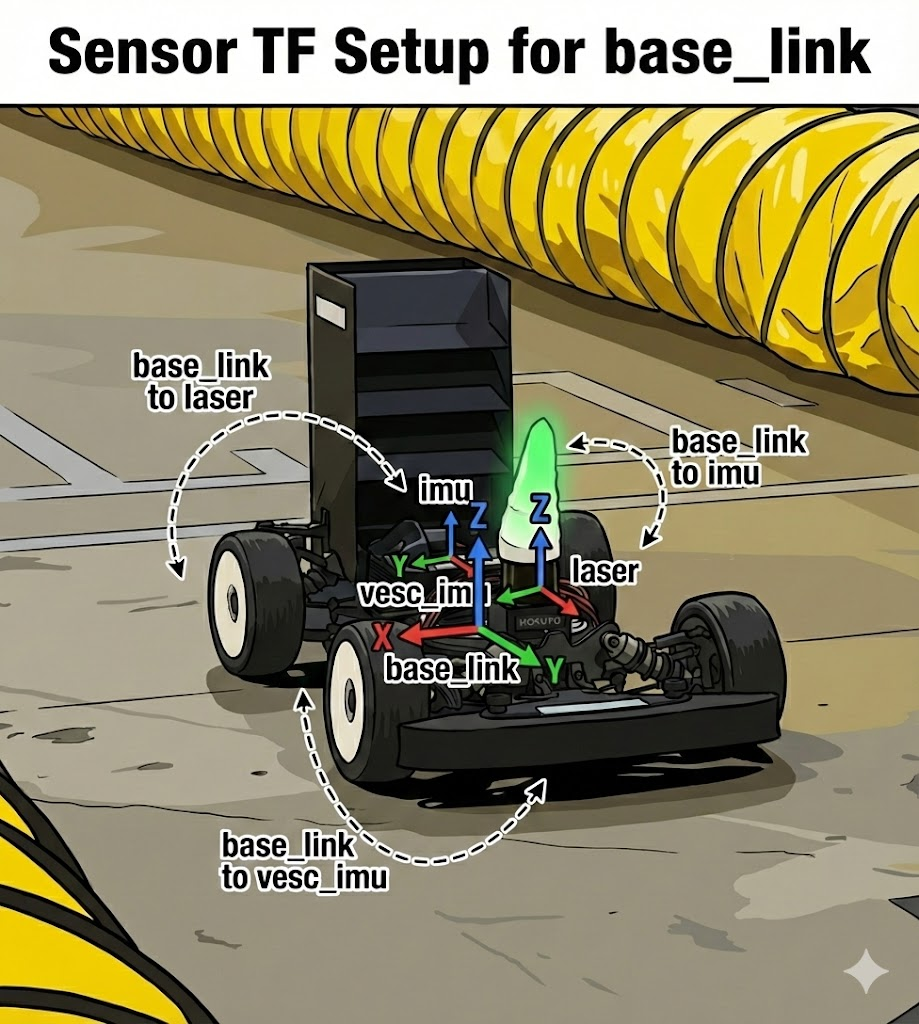
One of the first problems you hit when developing a robot is setting up sensor coordinate frames. To fuse LiDAR, IMU, and camera data, you must tell the system exactly where and in what orientation each sensor is mounted on the robot. This post covers how to set up sensor frames on the RoboRacer platform with ROS’s TF (Transform) system.
What Is TF?
TF is the ROS system that manages transforms between different coordinate frames. It defines spatial relationships — “the LiDAR is 30 cm forward of the robot center,” “the IMU is 6 cm to the left” — in a tree structure, and every frame must have exactly one parent.
The Full TF Tree
The tree we’ll build looks like this.
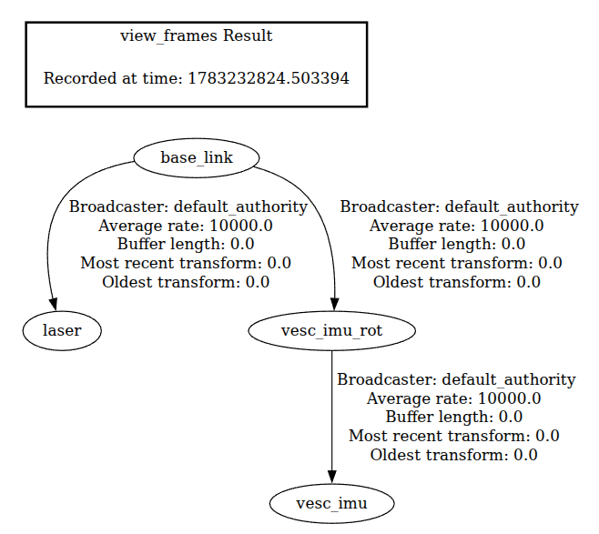
map → base_link: computed in real time by localization (out of scope here)base_link → sensor: the mounting position is fixed, so define it as a static transform (the topic of this post)
The Reference Frame: base_link
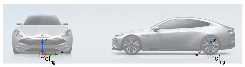
base_link is defined as the ground point at the center of the rear axle. An Ackermann-steering vehicle’s turning center is at the rear axle, which simplifies kinematics, and placing it at $z=0$ (the ground) keeps alignment with 2D mapping clean.
base_link → laser
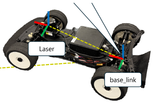
Measure and enter only the translation, and set rotation to 0. Instead, get the LiDAR as level as possible in hardware via roll·pitch.
base_link → vesc_imu: Why an Intermediate Frame
The IMU is connected in two steps, not one.
1
2
base_link → vesc_imu_rot   (translation only)
vesc_imu_rot → vesc_imu    (rotation only)
This split is because of two Cartographer constraints.
1. The tracking_frame constraint. To use the IMU in Cartographer, the tracking_frame must be the same as the IMU frame, or a frame that differs from the IMU frame only by rotation.
2. The gravity-initialization problem. If the IMU is mounted upside down and you use its frame directly as tracking_frame, the initial gravity-alignment step flips the entire map upside down.
So we create an intermediate frame vesc_imu_rot that has no translation offset from the IMU but is axis-aligned with base_link, and hand that to Cartographer. All of the mounting-orientation rotation is pushed into vesc_imu_rot → vesc_imu.
1
2
-- mapping_2d.lua
tracking_frame = "vesc_imu_rot",  -- aligned frame with no translation from the IMU
Configuration Example
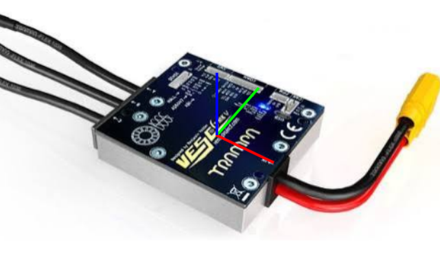
The IMU mounted on the VESC has the frame shown above.
Config file: stack_master/config/CAR/static_transforms.yaml
1
2
3
4
5
vesc_imu_rot_to_vesc_imu:
  parent: vesc_imu_rot
  child: vesc_imu
  xyz: [0.0, 0.0, 0.0]
  rpy: [0.0, 0.0, 1.5707963]   # choose per mounting orientation (see table below)
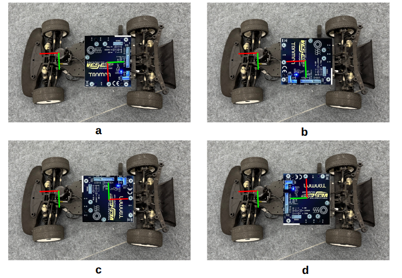
You only need to change the rpy value according to the VESC mounting orientation.
| Mounting | rpy |
|---|---|
| a | [0.0, 0.0, 1.5707963] (+90°) |
| b | [0.0, 0.0, 0.0] |
| c | [0.0, 0.0, 3.1415927] (180°) |
| d | [0.0, 0.0, -1.5707963] (-90°) |
Wrap-up
There are three key points.
- Define the reference frame (
base_link) at a physically clear point. - For the IMU with Cartographer, use an intermediate frame (
vesc_imu_rot) that separates translation and rotation as thetracking_frame. - If you don’t use the IMU in Cartographer, connecting
base_linkdirectly to the IMU is fine.
For basic concepts and how to measure, also see Sensor TF Setup Guide Based on base_link.